11
1.
Relay outputs:
2 relay outputs,
s
ignal relay, 1 Form C, 1A @ 30VDC, #2 on the left
2.
Voltage output: This is used to drive external devices such as a sensor. The voltage supplied depends on what power source
is used to power the ULTRA SERVER.
3.
Digital inputs: 2 digital inputs, 5VDC-48VDC (24VDC-48VDC must use the external resistor), #2 on the left
4.
Analog inputs: 2 analog inputs, isolated, #2 on the left
5.
CAN inputs (software not yet implemented)
6.
Digital input switches: IN2 on the on the left; Up position
–
Pull-up (PU), Down position - Isolated (ISO)
7.
Reset button
8.
Reload button
9.
RJ 45 connector
10.
USB mini connector for temperature/humidity sensor (Sold separately)
11.
Power input (12VDC-24VDC/USB(5V)
Caution: These units are ground isolated. Always connect so that power loop is only connected to the SERVER unit. Do NOT use
external ground connections. Doing so may damage the SERVER or POE originating device.
Power Connection
The SERVER power input is a Micro USB connector and marked as POWER on the enclosure. Connect the 12VDC power
supply to a suitable AC outlet and connect the barrel connector into the Micro USB connector, plus the other side of the
USB connector to the SERVER at the location labelled POWER, or you can use a USB cable to connect it to your computer
to power it on and find out the IP address from your network. Alternatively, you may also use POE. At this point the
GREEN/Boot LED should come on and start flashing indicating the SERVER is operating and is in the "Bootload Mode".
This mode allows the user to update the server software that is used on the unit. After about 5 seconds, the GREEN LED
will go off and the RED LED will start blinking once per second indicating the SERVER is operating in "Server Mode" and is
accessible on a network utilizing TCP/IP protocols.
Network Connection
Plug the Ethernet cable into the NET connector, the “Connection" LED on the
Ethernet connector side will come on if you connect to
network switch and a 100MHz network is available, otherwise it will remain off and the "Activity" LED should start blinking indicating
network activity.
CAUTION: WHEN YOU USE POE NETWORK SWITCH, DO NOT USE THE 12VDC POWER SUPPLY TO POWER THE SERVER AT THE
SAME TIME, IT WILL DAMAGE THE BOARD.
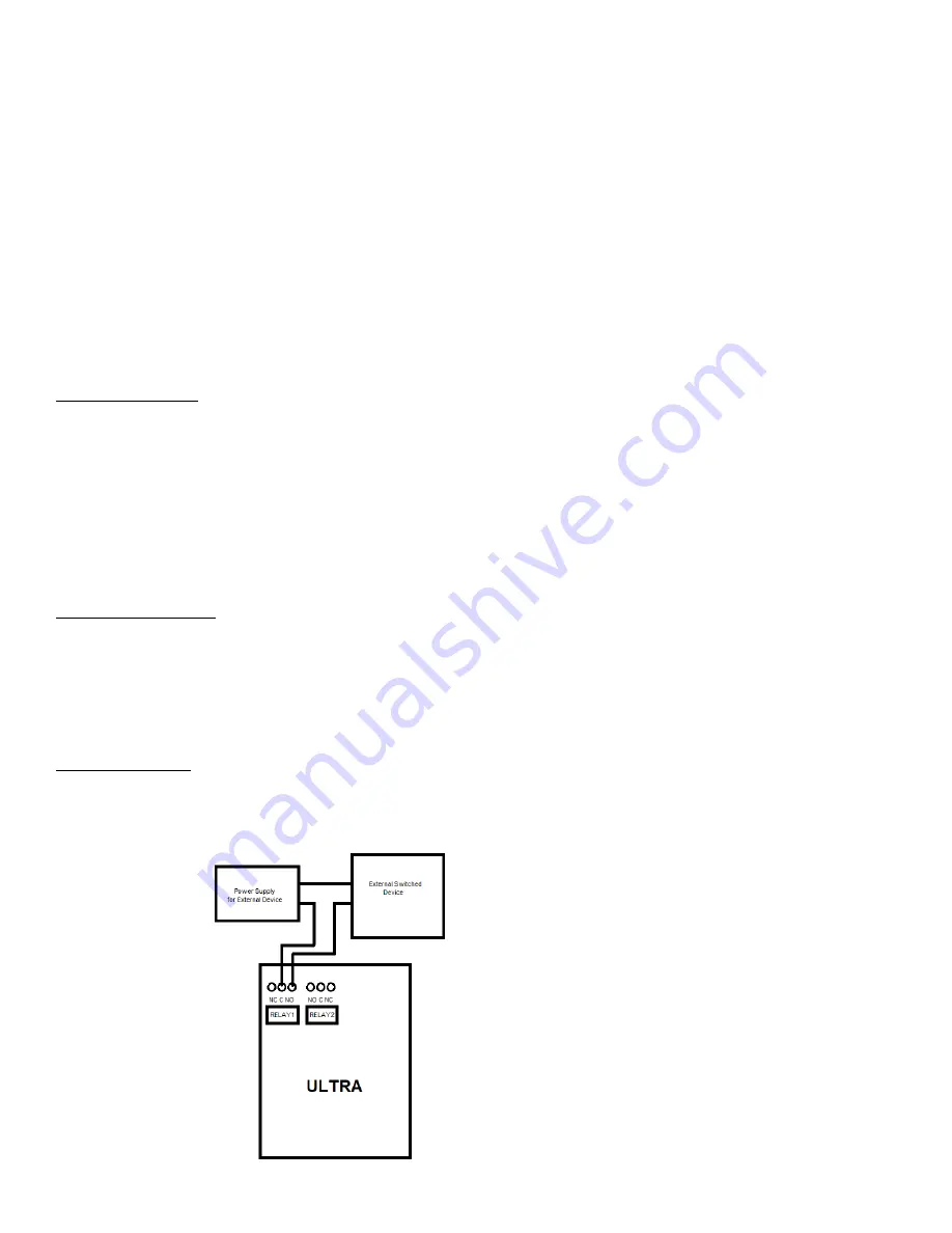
Relay Connection
The SERVER has 2 signal Relays (1 Form C, 1A @ 30VDC) with push-in spring connectors and are simply numbered OUT "1" and "2".
These are dry contact relays. The Ultra 300 units are designed for only low voltage control and should not have a voltage applied to
the relay greater than 30 volts. This is for your safety as well as to stay within the parameters of the parts and circuit board design.
Summary of Contents for iTrixx-Ultra 300
Page 2: ...2 ...


