12
The relays have 3 terminals labelled NO, C and NC which stand for Normally Open, Common and Normally Closed. When activated,
the relay moves the connection from C-NC to C¬NO. If you want to make a connection when the relay is activated, connect your
wires between C and NO. When the relay is activated C and NO will be connected together. If you want to break a circuit when the
relay is activated, make your connections to C and NC. When the relay is activated, the circuit will be broken (or open)
Voltage Output Connection
The SERVER has a voltage output that can be used to drive external devices. The voltage depends on what power source is used to
power the ULTRA SERVER. When USB is used the voltage out is 5V, when POE is used it's 12V out, when an external power supply is
used it is the same voltage as the power supply. There is always a small voltage drop and it is limited to 50mA. This is useful when
using the output to trigger a relay, or power a sensor. For higher voltage or higher current than our internal relay can handle, wire
the positive side of your external device to the "V" terminal, negative to "-" terminal.
Digital Input Connection
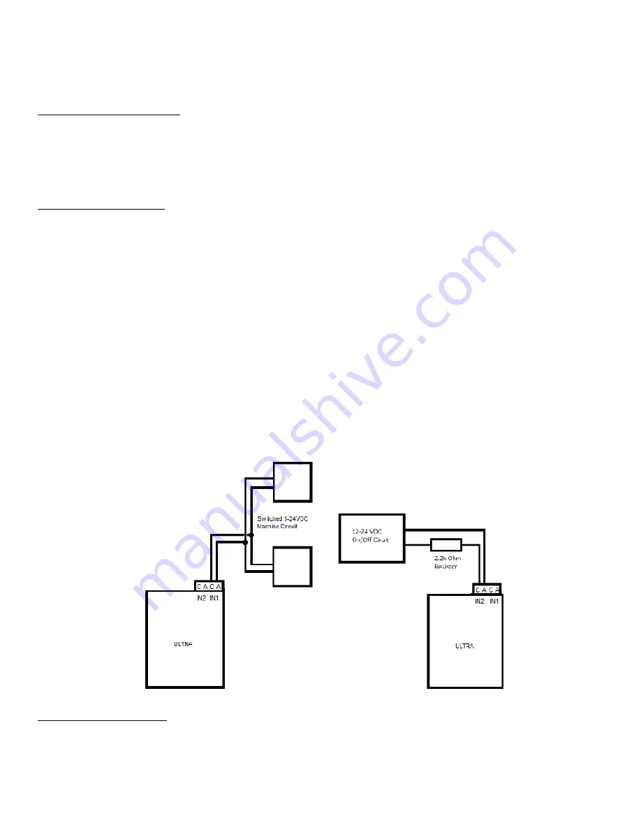
There are two digital inputs on the SERVER with push-in spring connectors, labeled as IN1 and IN2 on the enclosure. Each input has 2
terminals, marked as C A [C-cathode (-), A-anode (+)].
The digital inputs allow the SERVER to detect an external on/off state of a sensor. With this information the SERVER can display
whether an input is on or off, count events in a resettable or non-resettable counter, and calculate the frequency (such as for use as
a tachometer) or the period of the input. There are two modes of operation for the digital inputs -
PULL UP
and
ISOLATED
.
•
PULL UP
mode connects a 1K resistor to an internal voltage allowing you to use a simple switch (such as a magnetic door
switch) across terminals 1 and 2. This when the switch is activated a signal is sent to the input.
•
ISOLATED
mode allows you to directly drive the Ultra's optoisolator with an external voltage though an internal 1K resistor.
This voltage may be in the range of 5V to 24V supplying a minimum of 2mA or a maximum of 30mA to the optoisolator
diode. There is no other internal connection to this voltage so it is an isolated input.
These modes are selected by the switch on the SERVER (see
Board Layout Reference
), put the switch to down position for ISO and
up position for PU. These are set at the factory to ISO (down) by default.
Caution:
If you intend to use isolated mode, verify input switch is set to ISO before applying an external voltage. Doing otherwise
may damage the Ultra or POE originating device.
Analog Input Connection
The analog inputs allow the SERVER to read the value of external equipment. There are 2 analog inputs on the SERVER with push-in
spring connectors, labeled as AN1 and AN2 on the enclosure. Each input has 1 terminal. To wire a 2-wire analog sensor to the server,
wire the data wire to the analog input, ground wire to GND terminal. If your analog sensor comes with 3 wires, wire the data wire to
the analog input, ground wire to GND terminal, power wire to the V terminal.
Summary of Contents for iTrixx-Ultra 300
Page 2: ...2 ...


