background image

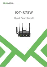
R75 Quick Start Guide

www.linovision.com

4

2. Hardware


Introduction

2.1


Overview

A.

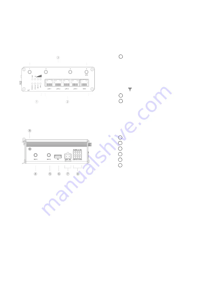
Front Panel of R75-5G

C. Left Side Panel

1

LED Indicator Area

POWER: Power Indicator
SYSTEM: Status Indicator
Wi-Fi: Wi-Fi Indicator
VPN: VPN Indicator
SIM : SIM Status Indicator

: Signal Strength Indicator

2

Ethernet Ports & Indicators

3

Cellular Antenna Connectors
(Connector 4 is for both GPS and cellular)

4

Wi-Fi Antenna Connector 1

5

Wi-Fi Antenna Connector 2

6

USB Port (Reserved)

7

Power Connector

8

Serial Port & I/O Ports

9

Grounding Stud

Summary of Contents for IOT-R75W

Page 1: ...IOT R75W Quick Start Guide...

Page 2: ...Guide Users could refer to the guide for instruction on how to log in the web GUI and how to configure all the settings The related documents are available on Linovision website https www linovision c...

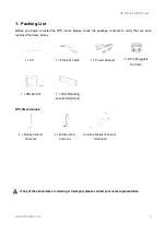
Page 3: ...y that you have received the items below 1 R75 1 Ethernet Cable 1 Power Adapter 1 8 Pin Pluggable Terminal R75 5G Antennas 4 Stubby Cellular Antennas 2 Stubby Wi Fi Antennas Antenna Magnetic Mount Opt...

Page 4: ...dicator SYSTEM Status Indicator Wi Fi Wi Fi Indicator VPN VPN Indicator SIM SIM Status Indicator Signal Strength Indicator 2 Ethernet Ports Indicators 3 Cellular Antenna Connectors Connector 4 is for...

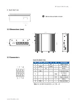
Page 5: ...ns mm 2 3 Connectors Serial Port I O Ports Note For RS485 model RXD A TXD B PIN RS232 RS485 DI DO Description 1 IN Digital Input 2 GND GND Ground 3 B Data 4 TXD Transmit Data 5 COM Common Ground 6 OUT...

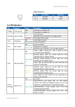
Page 6: ...ary SIM has been registered and is ready for dial up Blinking rapidly SIM1 as primary SIM has been registered and is dialing up now Static SIM1 as primary SIM has been registered and dialed up success...

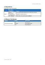
Page 7: ...Action Reset Blinking Press and hold the reset button for more than 5 seconds Static Green Rapidly Blinking Release the button and wait Off Blinking The router is now reset to factory defaults 2 6 Eth...

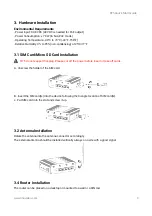
Page 8: ...rt hot plug Please cut off the power before insert or take off cards A Unscrew the holder of the SIM card B Insert the SIM card s into the device following the triangle location of SIM card s C Put SI...

Page 9: ...d in mm Use 2 pcs of M3 6 flat head Phillips screws to fix the DIN rail to the router and then hang the DIN rail on the mounting bracket It is necessary to choose a standard bracket Recommended torque...

Page 10: ...ps are based on Windows 10 operating system for your reference Note As remote access is disabled by default you can t access to the router s Web GUI if you connect PC to WAN port of the router But it...

Page 11: ...me admin Password password A Start a Web browser on your PC Chrome is recommended type in the IP address and press Enter on your keyboard B Enter the username and password click Login Double Click Int...

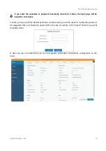
Page 12: ...ed for 10 minutes C When you log in with the default username and password you will be asked to modify the password It s suggested that you change the password for the sake of security Click Cancel bu...

Page 13: ...N to configure WAN parameters Take static IP configuration as an example DHCP client and PPPoE type are optional according to your requirements Click Save Apply button to make the changes take effect...

Page 14: ...erations A Click Network Interface Cellular Cellular Setting to configure the cellular info like APN and network type B Click Save and Apply for configuration to take effect If you select Auto the rou...

Page 15: ...ted it means SIM1 has dialed up successfully On the other hand you can check the status of SIM indicator If it keeps on green light statically it means SIM1 has dialed up successfully F Open your pref...

Reviews: