background image


15

The  DVR  system  can  be  configured  with  a  Single  View  Camera  Screen,  which  could  display  different 
camera viewpoints at 6-second intervals. More details on this mode are mentioned in 

Chap 7

 
Quad Camera View Screen 

1. 

Step 1: Click the Quad View Camera Icon on the right-side 

toolbar…………………………….……


2. 

Step 2: The screen will display four camera images in one screen. If your DVR system has 16 cameras, this 
view can be configured to display four different camera viewpoints at 6-second intervals. 


9-Camera View Screen 

1. 

Step 1: Click the 9-Camera View Icon on the right-side toolbar……………………………………..


2. 

Step 2: The screen will display nine camera images in one screen. If your DVR system has 16 cameras, this 
view can be configured to display nine different camera viewpoints at 6-second intervals. 


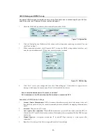
Figure 3-5: The Nine-Camera and The 16-Camera View Screen 


16-Camera View Screen 

1. 

Step 1: Click the 16-Camera View Icon on the right-side toolbar........................................................


2. 

Step 2: Sixteen camera images will be displayed in one screen.  


Full Screen Mode 

1. 

Step 1: Click the Full Screen View Icon on the right-side toolbar .....................................................


2. 

Step 2: The screen will display all or the selected cameras connected to the DVR in Full Screen Mode. If 

the system has 16 cameras, sixteen camera images will occupy the entire screen. 

3. 

Step 3: Click the right key of the mouse to resume original status. 


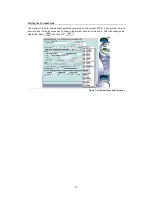
Figure 3-6: The Full-Screen Camera View Screen 

Summary of Contents for MEGAsys

Page 1: ...1 MEGAsys Linux DVR Digital Video Recorder User Manual...

Page 2: ...2...

Page 3: ...NGS 25 CHAPTER 08 ALARM SETTINGS 34 CHAPTER 09 ALARM LOG 40 CHAPTER 10 USER LOG 43 CHAPTER 11 CONFIGURING GENERAL PURPOSE I O 45 CHAPTER 12 PAN TILT ZOOM 48 CHAPTER 13 PLAYBACK 52 CHAPTER 14 REMOTE SU...

Page 4: ...4 Edition V 3 5 6 June 2007...

Page 5: ...high performance processor and quick I O connection not only provide you with the capability to monitor the camera in real time mode but also utilize the extra processing power to allow for a high fra...

Page 6: ...ting the hard disk drive cage and connectors Make sure that the cover is in a closed position when the DVR is not in use The cover has a lock in the middle so please follow these steps to open or to c...

Page 7: ...Memory can be upgraded to 256MB Power Management The DVR features sophisticated power management built into the complete BIOS Setup program Integrated Smart Charger Circuit which is designed to resta...

Page 8: ...o Recorder Front View 4 or 8 Channel Type 12 or 16 Channel Type Figure 1 1 Front View of the DVR Front Inside View Please refer to Figure 1 2 and the following descriptions to identify the components...

Page 9: ...ital Video Recorder comes with a built in 3 5 inch Floppy Disk Drive FDD 5 Floppy Disk Drive Eject Button Press this button to eject the floppy disk in the FDD 6 Floppy Disk Drive LED When the LED is...

Page 10: ...riptions to identify the components on the rear side of the Digital Video Recorder Figure 1 3 Rear View of Digital Video Recorder 1 Power Fan This is used to cool the power supply 2 System Ventilation...

Page 11: ...l power outlet 10 Voltage Switch The voltage switch regulates the voltage specifications of 110 220V as required for different regions Switch the voltage according to your region s requirements 11 Pow...

Page 12: ...LAN Cable to the Ethernet LAN Card 4 Connect the Keyboard and the Mouse to their respective PS 2 Ports 5 Connect the Printer to the Printer Port COM1 is used to connect a MODEM with the 4 or 8 channel...

Page 13: ...ce Figure 2 2 The first viewable screen Main Screen The first viewable screen not only gives the user a first glance at the GUI Graphical User Interface but also shows all of the connected cameras The...

Page 14: ...enu 4 Log on Icon Click this icon to enter the Log on Shut down Menu 5 Single View Icon Click this icon to run in Single view mode 6 Quad View Icon Clicking this icon will display four camera images o...

Page 15: ...or just double click the respective camera image on the main screen 5 Zoom out Icon Clicking this icon will zoom out the selected camera images Or you can just click the right key of the mouse to zoom...

Page 16: ...do the following 1 Step 1 Click the Log on Icon on the right 2 Step 2 Under User name field type in or select admin default under Password field type in the password or admin default 3 Step 3 Click t...

Page 17: ...xplaining what that icon does Entering the DVR Main Screen the icons on the right side may be used to control different functions of your DVR The following brief description explains how to activate t...

Page 18: ...right side toolbar 2 Step 2 View the video database under the Playback Screen Click on a selected file and open the recorded data The red circle indicates the playback image Figure 3 3 The Playback Sc...

Page 19: ...e screen will display nine camera images in one screen If your DVR system has 16 cameras this view can be configured to display nine different camera viewpoints at 6 second intervals Figure 3 5 The Ni...

Page 20: ...gs of each camera 1 Click the Setup Icon on the Main Screen to enter the camera settings screen 2 Click the Diamond Icon to choose the camera you want to configure 3 The small window under the camera...

Page 21: ...y for i Hue This is the attribute of colors that permits them to be classed as Red Yellow Green Blue or an intermediate between any contiguous pair of these colors ii Saturation This is the degree of...

Page 22: ...ifferentia A factor that distinguishes differences among images relating to entity state or class from 1 to 10 For example assuming the value to be 1 once the second image is different from the first...

Page 23: ...city of the hard disk of your DVR Schedule your recording according to your requirements Once the DVR is in recording mode various scheduling times should be set for each different video camera Follow...

Page 24: ...ecording every month Figure 5 5 Monthly Schedule Settings 4 After you have selected the record mode and record option choose the camera you want to configure you can also choose the camera first and t...

Page 25: ...cameras 1 Select the Once option 2 Select the serial number of the camera you wish to configure Then the selected camera will appear in high light mode 3 Select the recording duration Figure 5 6 Dura...

Page 26: ...ll permanently delete all related information from the hard disk drive thus freeing up disk space 1 Select the recorded scheduled period from the list Figure 5 8 Deleting Schedule Settings 2 Click the...

Page 27: ...e or configure users for the DVR system 1 Click the Setup Icon on the Main Screen 2 Click the Account Tab Figure 6 1 Account Tab Window 3 Enter the name of the user followed by a specified password 4...

Page 28: ...ow Playback to enable users to playback the recording files 13 Click Allow Control PTZ to enable users to control PTZ cameras 14 Select a checkbox to mark a given camera as available to the user being...

Page 29: ...se steps to set up your DVR machine s 1 Click the Setup Icon on the Main Screen 2 Click the System Tab Figure 7 1 System Tab Note NAS NTP and Audio are optional please read the Appendix to understand...

Page 30: ...ccess message which means the domain name Note will be enabled after 3 mins Note A complete domain name is Account dvrsite net Ex Account name is dvr124 enter http dvr124 dvrsite net to connect the DV...

Page 31: ...tem automatically and the IP field will revert to disconnect again If users chose to connect the external network by modem dialup DVR will use modem dialup for alert e mail delivery the Network connec...

Page 32: ...guration files may also be recopied to allow quick setup of multi DVR systems The system supports a variety of user selectable back up devices 1 Click Backup Config 2 Then the screen will list the bac...

Page 33: ...k is automatically adjusted according to the system BIOS If the system time is incorrect then it may be necessary to change the system clock and time zone After the changes are made click Apply and th...

Page 34: ...checkbox next to Recycle Rec Figure 7 10 Recycle Rec Option 3 Click Apply then OK to activate the changes Auto Login A second option is to give the administrator and other users Auto Login status when...

Page 35: ...to activate the setting Number P Frames after I Frame The Number P Frames after I Frame setting refers to the manner in which MPEG 4 compression will be implemented by the DVR system An I frame is th...

Page 36: ...VR system from remote site using telnet utility for maintenance For security consideration user can disable this function as following 1 Click the System tab 2 Under the Others item uncheck the Enable...

Page 37: ...ports on Virtual Server or you must fill in the three TCP ports in this item that corresponding to the three ports assigned by Virtual Server Example Network Environment please consult the Net Supervi...

Page 38: ...Enable Trigger Period and Alarm Triggering Device 1 Click the Alarm Tab 2 The first column for user to select cameras DI and other alarm settings 3 The second column for user to set the pre alarm rec...

Page 39: ...on To set up other record durations tick off the entire Enable field first then select Enable under Trigger Period to set the record duration 5 Click Record Tab 6 Click Add button 7 Click Apply then O...

Page 40: ...ition Follow the instructions below to set the Alarm Message 1 Click the Alarm Tab first 2 Select the Camera Din Disk full Disk failure or No Signal 3 Select a Trigger Period 4 Click the Message Tab F...

Page 41: ...eriod of 1 to 10 seconds may be set see picture below 5 Repeat Times is used to set the number of times you d like to trigger the alarm 1 to 10 times can be set see picture below Figure 8 7 Voice Tab...

Page 42: ...in the appropriate email address An additional email address may be specified in CC 6 Adjust the Send parameter as desired to specify the number of seconds of video you d like to send in the email a v...

Page 43: ...onds the delay time may be set from 0 to 999 seconds 8 Under the Duration there are settings of 0 to 999 seconds to choose from A setting of 0 seconds means permanent triggering 9 Then click Add and t...

Page 44: ...triggering event Thus you can handle the entire alarm status conveniently The log is simple and allows the administrator only two options a to delete a single log b to delete all log files Follow the...

Page 45: ...task Export Log Data While viewing Alarm Log data if you wish to export a section of a file to save in addition do the following 1 Click Export icon and the following window will appear Figure 9 4 Ex...

Page 46: ...the file name will be modified please change it now After that click OK Figure 9 6 Store Alarm Log File Screen 6 If this data stored please click OK in the confirmed message box Figure 9 7 Confirmatio...

Page 47: ...nly be deleted or else the entire log file can be deleted Follow these few steps to delete files Deleting One Log 1 Click the User Log Tab 2 Select the file you wish to delete Figure 10 1 User Log Sel...

Page 48: ...44 Figure 10 3 Confirmation Window 4 Click Confirm to continue or Cancel to reset 5 Click Apply then OK to complete the task...

Page 49: ...e 4 channel type DVR may have four DI DO The 8 channel type may have eight DI DO the 12 channel type may have eight DI DO and the 16 channel type may have 16 DI DO The related DO relay output and sens...

Page 50: ...connection of the sensor When the alarm is triggered the circuit connected to the alarm sensor input of the DVR will be closed Normal Closed NC When the sensor is of the NC type DI is connected to th...

Page 51: ...mally open when an alarm is triggered The DO relay output of the DVR will transition from open to closed Normal Closed NC If the DO relay output is set to be normally closed when an alarm is triggered...

Page 52: ...IC Protocol only support for WV CS850 WV CS854 Traditional Protocol 6 Dynacolor Protocol D7722 D77HO 7 MD Nicecam MP1000 MD1800 8 Katatel 312 Protocol The user should contact their dealer for informat...

Page 53: ...neuver the PTZ camera at different speeds click the drop down list next to Speed Users can set the speed range from 0 7 2 Using the Dome controls at the bottom left of the PTZ window users can configu...

Page 54: ...econd to 255 degrees per second and the duration Time range from 0 to 255 seconds to make adjustments to preset speed and duration time for the PTZ camera 4 Once complete click the Save button 5 To vi...

Page 55: ...d Group 4 then click Set Group button Function To operate presets 5 to 16 in the mode of Run Sequence PAN SCAN This DVR system allows the user to set up the PTZ camera to scan from the SET START to SE...

Page 56: ...a or by checking the list of all files you are able to choose record files At the bottom of the screen you will notice a set of icons These icons will help later when using the playback image Figure 1...

Page 57: ...o forward at 1 2 speed press twice for 1 4 speed press three times for 1 6 speed Click this icon to fast forward the file and the optional speeds are 1x 2x 4x 6x 8x 10x Press once to go at the speed o...

Page 58: ...t a date and time from the calendar Figure 13 5 Calendar Camera Selection 3 Select a camera 4 Click Search to list the desired files or click List to show all the files 5 Then the recorded database wi...

Page 59: ...Double click the selection or click Open The video from the selected file will appear in the top left hand corner of the Main Screen Figure 13 8 Recorded Data Playback 8 Click Play from the Bottom To...

Page 60: ...56 10 Double click the image again to enlarge Figure 13 10 Full size Playback Image 11 To reduce the size or go back to the original size right click...

Page 61: ...A database of all the alarm triggered playback files will appear Alarm Log Figure 13 11 Alarm Log 3 Please select the file you want from the alarm video log Double click it or click Open The selected...

Page 62: ...in the Tag name first 3 Click the Insert button the information about the Camera Tag time and Description the camera name will be added to the system automatically and then be listed out Figure 13 14...

Page 63: ...b The first time the program is used You need to export the playback program b Due to the transcoding the image is not so clear Note1 The installation program for playback program is DvrActiveXSetup e...

Page 64: ...two functions Figure 13 18 Sharp Image 1 Open the recorded image 2 Click on this icon to blur the image 3 Click on this icon to sharpen the image The Blur Icon and the Sharpen Icon are at the same po...

Page 65: ...ired location The images below will demonstrate this function Figure 13 20 Viewing More Than One Playback Image Printing an Image 1 Click the snapshot icon to pop up a new window to show the image Fig...

Page 66: ...nt icon to print out the image individually If you print it out successfully the screen will pop up a new window to show you Please click Confirm to indicate that the files have printed out Figure 13...

Page 67: ...ndow you are able to easily and conveniently operate your Digital Video Recorder remotely 1 Click the Setup icon from the Main Screen of the DVR system 2 Click the System Tab Figure 14 1 System Tab Sc...

Page 68: ...een has four sections to it They are Monitor Playback Setup and Logout Monitor Click this area to monitor image preview and real time recording Playback Click this area to view playback of the recorde...

Page 69: ...n the real time monitoring preview screen will appear every camera connected to the DVR has its respective screen These are static images taken from the respective cameras Figure 14 5 Remote Monitor S...

Page 70: ...tor to view the particular camera you choose 8 Then click Refresh to refresh the static preview images Real Time Monitor Window The Real Time Monitor Window is the key window of remote monitoring user...

Page 71: ...as 4 FPS 1 4 Cameras 8 FPS Click or to adjust the Max speed 0 30 FPS as below Figure 14 8 Adjust maximum display speed Click icon to export images to HDD or print it out via printer as below Figure 14...

Page 72: ...n is the DVR status monitor and PTZ control icon when clicked during real time monitoring the right side of the window will show the following information 1 Recording time is displayed 2 If recycling...

Page 73: ...formation 1 An indication whether each camera has an alarm event for motion detection a green light shows normal status a red light is alarm mode 2 An indication whether each camera has an alarm event...

Page 74: ...le 8 Tag File Button Click this button to find a file by its tag 9 Snapshot Button Click this button to take a snapshot and print it out 10 Export Button Click it to export and save an image to output...

Page 75: ...nce you have clicked the File icon 2 A new pop up window will appear allowing you to select the camera and the time you wish to preview Figure 14 15 Playback by File Remotely 3 Click the Search button...

Page 76: ...Alarm 2 Select one alarm file click Open to play it 3 Click the Delete button to delete one alarm file Figure 14 18 Alarm File Taking a Snapshot Whenever you find an abnormal status on the screen you...

Page 77: ...and save it onto your local hard drive 1 Click the Export button 2 Select an export option and click the Export Figure 14 20a Export Option 3 Select an exporting duration 4 Select if you also need to...

Page 78: ...window will list all the tagged files The following tells how to produce a tagged file 1 Click the Tag Add button 2 After entering the Tag Name click the OK button Figure 14 21 Export Duration 3 Clic...

Page 79: ...e X Object according to the information provided in Appendix F All remote functionality is set up similarly to the local machine The major difference is the way the interface looks On the left side of...

Page 80: ...click to choose the default value 50 50 50 50 8 Motion Detection Frame Setting a Hidden Area Show Area button Click this button to hide the motion detection frame that has been drawn click it again t...

Page 81: ...anging the settings click the OK button to complete the setting or click the Cancel button to reset Remote Schedule Configuring Click the Schedule link to view the Remote Schedule Settings Figure 14 2...

Page 82: ...ow Delete Delete all scheduled Settings Choose the scheduled setting items of and then click Delete Delete All to delete the files Remote Account Settings Entering the Account Settings screen as the A...

Page 83: ...setup furthermore As a normal user your access authority is limited in some aspects When you log on a window will appear as below Figure 14 32 Normal Account Screen Click Monitor to show the camera s...

Page 84: ...ll be lost disabling any further operations 2 The version number Version 3 5 4 will be visible in the header 3 Internet In this field you can setup the info regarding to Internet and modem dial up a D...

Page 85: ...ed logs about the alarms will be listed out including the cause triggered time and the descriptions of the triggering condition Through the use of the logs you will be able to view the status of all o...

Page 86: ...eviously check individual logs respectively or click in the checkbox next to Select All and then click Delete to delete unwanted logs Remote GPIO Settings The operation on remote GPIO is the same as w...

Page 87: ...tional DAS Direct Attached System cannot meet these requirements anymore Steps 1 Click the Setup icon on the main screen 2 Click the System tab 3 Click the NAS button to popup the NasSetup windows Fig...

Page 88: ...equal to the Lowerbound This procedure will be continued till the free space is more or equal to the Upperbound 9 Backup Period DVR will not keep archiving data to NAS the Backup Period is the time in...

Page 89: ...to synchronize the clock of DVR to another reference time source in the network Steps 1 Click the Setup icon on the main screen 2 Click the System tab 3 Click the NTP button to popup the NTP setup wi...

Page 90: ...active Not to active the selected NTP server 7 Delete Delete the selected NTP server in the list 8 Sync Period Click the Hourly Daily Weekly or Monthly you can have DVR be timed every hour day week o...

Page 91: ...audio playback via built in audio device of motherboard Steps 1 Click the Setting icon on the main screen 2 Select System Settings 3 Click the Audio button to pop up the setting window Figure C 1 Clic...

Page 92: ...Low The better quality the bigger file size is needed Playback Property Click Mute for mute mode or adjust the volume slider for volume control Note The volume is irrelative with the file s capacity...

Page 93: ...89 2 The real time monitoring and playback screen in mute mode Click the mute icon to switch to audio mode Figure C 5 Real time monitoring screen in mute mode Figure C 6 Playback screen in mute mode...

Page 94: ...e playback clips according to cameras and date time Figure D 2 Playback setting for the date time and camera 3 Click the slice4 slice9 or slice16 to select 4 camera 9 camera or 16 camera synchronous m...

Page 95: ...91 Figure D 3 Zoom out the image of camera...

Page 96: ...Never use a damaged cable A damaged cable is not only a fire hazard it may also cause a short circuit resulting in irreparable damage to the Digital Video Recorder Isolating the Problem The problems...

Page 97: ...utput System BIOS These critical malfunctions prevent the Digital Video Recorder from operating at all or could cause incorrect and apparent results An example of a critical error is CPU mal function...

Page 98: ...get into the system the window will pop up a warning screen which is about the Active X setting the details are as follows Figure F 1 Warning Window The user could check Always trust content from Soft...

Page 99: ...95 Figure F 3 Objects Selection Figure F 4 Install Location Selection Figure F 5 Installation Window After finishing installation then click Close...

Page 100: ...e on the camera image by drag a frame sized window over the desired motion detection area Continue to do this until all the needed frames have been drawn up to six detection frames Figure G 2 Camera V...

Page 101: ...e alarm is trigger Motion Enlarge Motion Enlarge Display Time Switch Time 9 On the right hand side of the camera display window select the Schedule as the record mode Figure G 4 Camera Info Field 10 C...

Page 102: ...n detection on each camera can be configured under the first setting screen Cam However user may not be aware when motion detection is triggered Under Alarms screen arm time period can be set up so as...

Page 103: ...the Setup icon on main screen 2 Click the Schedule tab Figure G 6 Schedule Settings 3 Click Weekly tab to set the day and time for recording for every week 4 On the REC Option window select the date...

Page 104: ...rol Feature 1 Click the Setup icon on the Main Screen 2 Click the System tab Figure H 1 Systems Settings Page Login Control Function 3 In the Host Lan window click Login Control tab Figure H 2 Login C...

Page 105: ...Control Function 3 In the Host Lan window click Login Control tab 4 In the Login Control window deselect the Only the following IPs can login feature Figure H 5 Login Control Screen 5 Click Exit to sa...

Page 106: ...ze under the Login Control list 1 First of all use the computer with the authorize IP address recorded on the Login Control list for example PC IP 192 168 42 147 Start up the IE browser enter http 192...

Page 107: ...ss is found on the LAN the Remote Surveillance System screen will appear as below By typing admin default for both User Name field and Password field Figure H 8 DVR Remote Logon Window 6 An error mess...

Page 108: ...20 src rpm GPL 14 gawk 3 0 6 1 src rpm GPL 15 initscripts 5 83 1 src rpm GPL 16 net tools 1 57 6 src rpm GPL 17 ed 0 2 19 src rpm GPL 18 grep 2 4 2 5 src rpm GPL 19 gettext 0 10 35 31 src rpm GPL 20 t...

Reviews: