background image

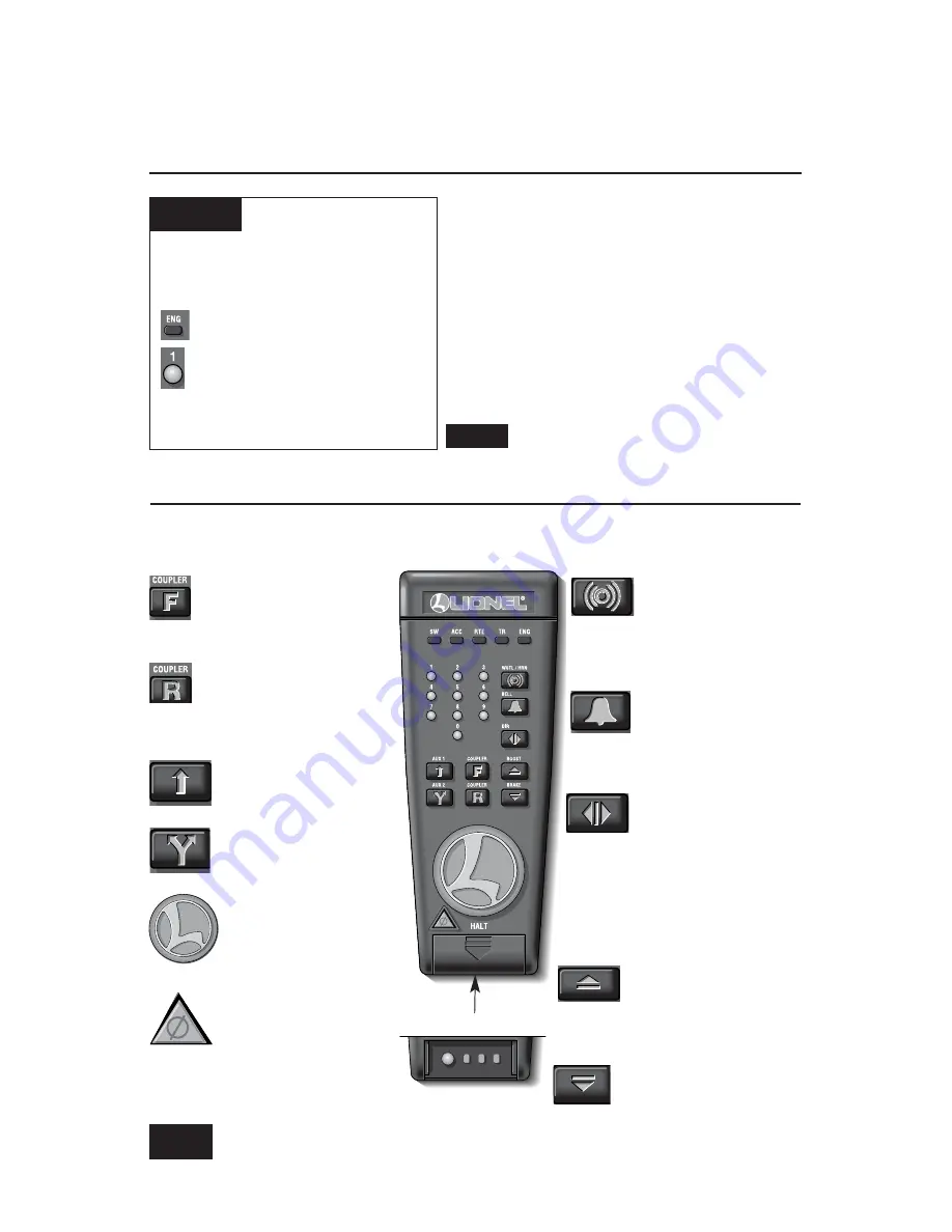
Front coupler releases.

Coupler release

sounds.

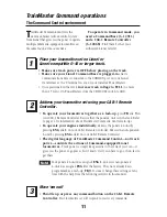
Running your powered locomotive in the TrainMaster Command
Control environment

TrainMaster Command operations

Y

our Command-equipped powered locomotive
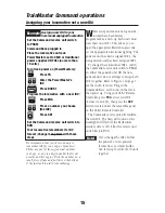
comes factory-programmed with an ID# of “1.”

To operate your powered locomotive without the non-
powered unit, set PowerMasters to CMD or set all
power supplies on full (no more than 19 volts). Press

ENG

and 

1

on your CAB-1 Remote Controller. Turn

the throttle or press any command button; your
powered locomotive is ready for Command Control
operations.

To operate the both units in a lash-up, see
page 16.

Address Locomotive #1

PowerMasters set to CMD or
traditional power supplies ON FULL
(no more than 19 volts)

Press ENG

Press 1 (the ID#)

Throttle up/press any command
button

Example

Note!

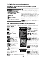
Press 

AUX2

to turn

your locomotive set’s
headlights on and off.

Activates the numeric
keypad. 

Air release

sounds.

Press 

HALT

to shut down

all PowerMaster electrical

output on your railroad.

Stops all Command-equipped
Lionels in operation.

Turn the 

THROTTLE

to the right to 

accelerate, left to

decelerate. 

CAB-1 Remote Controller commands for your locomotive set

Press 

WSTL/HRN

to

activate the horn, release

it to discontinue. 

MultiHorn

diesel horn sound. 

Press 

DIRECTION

—the

locomotive decelerates to

a complete stop; turn the throttle
up, and the locomotive will
accelerate in the new, opposite
direction. There is no neutral state.

Diesel air-release sound.

Press 

BELL

once to

activate the bell, again

to discontinue. 

Diesel

mechanical bell sound.

Press and hold 

BOOST

for extra power. Release

BOOST

and return to the

locomotive set’s previous speed. 

Press and hold 

BRAKE

to

slow down or stop. Release

BRAKE

and return to the previous

speed. 

Squealing brake sounds.

Rear coupler releases.

Coupler release

sounds.

AUX 2

AUX 1

Use HALT only in 

emergency

situations.

Note!

SET

L

M

H

Beneath this panel

12

RailSounds sound system effects are in bold italic. (Only the powered A-unit
features sounds.)

Summary of Contents for Union Pacific ALCo PA

Page 1: ...Lionel Union Pacific ALCo PA Passenger Set Owner s Manual 73 1712 250 8 03 SYSTEM featuring and ...

Page 2: ...lectroCouplers in Command Tire Traction Diesel smoke generator in both A units Interior lighting Features of the aluminum passenger cars StationSounds in diner Die cast metal sprung trucks and operating couplers with hidden uncoupling tab Separately applied metal details including roof vents and grab handles Detailed end vestibules Metal frames Extruded aluminum bodies Authentically detailed inter...

Page 3: ...ds for your locomotive set 12 CAB 1 Remote Controller numeric keypad commands for your locomotive set 13 Tuning your locomotive set s performance 14 Assigning your locomotive set a new ID 15 Building a lash up 16 Reprogramming the Command reverse unit to restore features 17 Maintaining and servicing your locomotive set Adding fluid to your locomotive s smoke generator 18 Lubricating your locomotiv...

Page 4: ...ent Virtually all Lionel and Lionel compatible alternating current transformers are suitable Do not power your locomotive set with direct current DC Damage to sensitive electronic components may occur When you first power up your track the powered locomotive will wait between three and eight seconds as it listens for digital language from the TrainMaster Command Base available separately When the ...

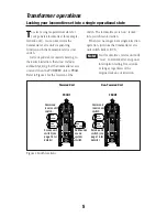
Page 5: ...he locomotive set is now locked into your chosen direction When you no longer want single direction operation just slide the Command reverse unit switch back to RUN Your locomotive s reverse unit will reset to forward after any power interruption lasting five seconds or longer regardless of the original locked out direction Locking your locomotive set into a single operational state Transformer op...

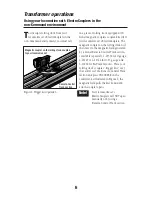
Page 6: ...ated by a Lionel Remote Control Track section available separately 6 65530 for O gauge 6 65149 or 6 12746 for O 27 gauge and 6 12020 for FasTrack layouts Place your rolling stock s coupler trigger disc over the central coil of a Remote Control Track section and press UNCOUPLE on the controller As illustrated in Figure 2 the magnetic field pulls the disc downward and the coupler opens Your locomoti...

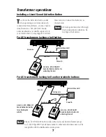
Page 7: ...re nut Red wire Red wire The no 610 5906 001 button works with any Lionel AC transformer except no 6 4690 Type MW Transformers made by other manufacturers may not be compatible with the RailSounds sound system Note To activate the bell and whistle sounds when operating your locomotive with conventional transformers you may need to install Lionel no 610 5906 001 Sound Activation Buttons available s...

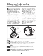
Page 8: ...esel locomotives for the ultimate in realism You may choose to install a nine volt alkaline battery in the powered locomotive set This ensures interruption free operation of the RailSounds sound system The battery harness is located at the rear of the engine beneath the rear hatch Gently lift up and unsnap the rear hatch as shown in Figure 3 below to access the battery harness Snap the battery har...

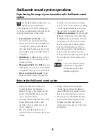
Page 9: ... sound system in the world Four diesel roar levels Your locomotive set s speed automatically determines the level of diesel RPM roar If you prefer you may set the level to idle half throttle three quarters or full speed output using your CAB 1 Remote Controller MultiHorn A different horn sound at different speeds a RailSounds sound system exclusive Mechanical bell Press BELL on your CAB 1 Remote C...

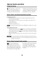
Page 10: ...moke unit and lights are connected directly to track power Do not exceed 14 16 volts for extended periods Doing so will cause damage to the locomotive Odyssey System operations Odyssey System conventional transformer operation The Odyssey System The Odyssey System is a cruise control for your engine Once the speed is set see below your engine will maintain a constant speed no matter what loads the...

Page 11: ...by pressing ENG and 2 on your CAB 1 Remote Controller The digital language of TrainMaster Command Control not track power controls the actions of Command equipped Lionel locomotives Track power is simply like gasoline in the tank of your car it gives you the power to go places but it doesn t tell you where to go or how fast to get there Your powered A unit was assigned ENG 1 and your non powered A...

Page 12: ...elease sounds Press HALT to shut down all PowerMaster electrical output on your railroad Stops all Command equipped Lionels in operation Turn the THROTTLE to the right to accelerate left to decelerate CAB 1 Remote Controller commands for your locomotive set Press WSTL HRN to activate the horn release it to discontinue MultiHorn diesel horn sound Press DIRECTION the locomotive decelerates to a comp...

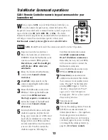
Page 13: ...4 Lowers the volume of the RailSounds sound system Sound volume decreases 5 Activates the RailSounds sound system shutdown sequence Just like the real thing your locomotive set s RPMs must be at idle for shutdown to occur Press 6 repeatedly to lower RPMs until they won t descend further Your locomotive is now at idle Press 5 to initiate the shutdown sequence following the CrewTalk communication so...

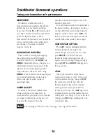
Page 14: ...igure 3 on page 8 for the location Turn the adjustment knob left or right to reach the desired volume level For quick remote control of volume below the master setting for example muting use the CAB 1 Remote Controller numeric keypad s volume control Press AUX1 and then 4 on the numeric keypad to lower the overall RailSounds sound system output HIGH VOLTAGE SETTING Press SET and the headlight will...

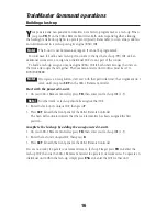
Page 15: ... powered A units have been factory programmed as a lash up both units must have their own ID s This allows you to open the appropriate ElectroCouplers and set the appropriate directional lighting The powered unit has been assigned ID 1 the non powered unit has been assigned ID 2 To change these individual ID s switch the Command reverse unit switch to PRGM on either the powered unit OR the non pow...

Page 16: ...t particular unit the assignment isn t saved until you press SET on the CAB 1 Remote Controller Start with the powered A unit 1 On your CAB 1 Remote Controller press TR then enter your lash up ID 1 9 No other track or lash up should be assigned that ID 2 Enter the lead unit s unique ID then press F 3 Press SET beneath the front panel of the CAB 1 Remote Controller The horn will sound to indicate t...

Page 17: ... the following steps STEP 1 Move the switch on your locomotive from RUN to PRGM STEP 2 Plug in your Command Base STEP 3 Place the locomotive on track then turn on power to your track STEP 4 Press ENG then input the locomotive s ID Press SET STEP 5 Press ENG the ID AUX1 then press 8 for your locomotive STEP 6 Turn off power to your track and wait ten seconds STEP 7 Remove the locomotive from your t...

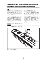
Page 18: ...oduction decreases add four to eight drops of smoke fluid in the same manner Additional smoke fluid 6 62909 is available from your Lionel dealer To turn off the smoke generators slide the smoke unit switch at the bottom of each locomotive to the NO SMK position see Figure 1 on page 5 for the location of this switch When the smoke generator is on be sure that there is smoke fluid in the smoke gener...

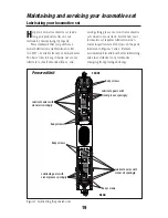
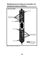
Page 19: ...motive set requires lubrication when visual inspection reveals dryness on the parts indicated in Figures 5 and 6 Remove accumulated dirt and dust before lubricating and always lubricate any locomotive emerging from prolonged storage 19 Lubricating your locomotive set Maintaining and servicing your locomotive set FRONT REAR Powered Unit Figure 5 Lubricating the powered unit Lubricate axles with Lio...

Page 20: ...ive set continued FRONT Non Powered Unit Figure 6 Lubricating the non powered unit Lubricate axles with Lionel oil sparingly Lubricate axles with Lionel oil sparingly Body screws Body screws Body screws Body screws Lubricate the axles on the non powered B unit sparingly Note ...

Page 21: ...active effort of the unit allowing it to pull more cars at once During the course of normal operations the traction tires may become worn out Because you must remove the trucks and the side frames to access the wheels we recommend that you have the traction tires replaced by your authorized Lionel Service Center See the Lionel Service section on page 48 for more information ...

Page 22: ...ormal operations the lamps may require replacement The LEDs are expected to last for the life of the locomotives Due to the delicate wiring and soldering operations we recommend that you have the replacement done at a Lionel Service Center Refer to the Service Center list included with this set for the location nearest to you See the Lionel Service section on page 48 for more information ...

Page 23: ...uctor boarding announcement or on first power up All Aboard First Short Horn Running n a Conductor welcomes passengers and Whistle Blast collects tickets Second Short Horn Running n a Steward announces first seating in Whistle Blast the dining car Third Short Horn Running n a Steward makes lounge car Whistle Blast announcement Bell started Running n a Conductor announces the next stop Short Horn W...

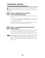
Page 24: ...rack increase track voltage to FULL If you are using any PowerMasters be sure to slide the CMD CONV switch to CMD Address your StationSounds Car using your CAB 1 Remote Controller Turn power on then press ENG 1 to operate the StationSounds Car individually with the powered A unit Press TR 9 to operate the car with the locomotive lash up You are now ready to activate the RailSounds sound system fea...

Page 25: ...ommand table Some functions described above require you to press two keys in sequence using the AUX1 button as a prefix before the numeric key Pressing the same numeric key without the prefix will produce a different function If you have pressed the AUX1 button for other reasons e g to open the keypad on your CAB 1 Remote Controller you can still trigger a non prefixed function by pressing the num...

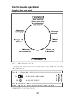
Page 26: ...rs Press Station PA announces train departure Press Conductor calls All Aboard Train pulls out of station and starts trip Press Conductor welcomes the passengers Press Conductor collects the tickets Press Steward announces first seating in the dining car Press After a minute and a half steward announces second seating in the dining car or lounge car service Press After 3 minutes steward announces ...

Page 27: ...out of station and starts trip NOTE The script sequence for the train in motion is the same as on the previous page IN STATION Now arriving Watch your step Now departing All aboard Welcome aboard Dining car first seating Tickets please Next stop coming up Lounge car drinks Dining car second seating EN ROUTE Note how the pattern can be repeated for multiple stops Figure 7 StationSounds on a round t...

Page 28: ...ash up to coordinate the announcements StationSounds will not play if the car shares an ID with any other engine If the StationSounds Car does not share an address with the lead unit you must address the StationSounds Car s specific ID number to play an announcement As you experiment with your StationSounds Car you will note that it is possible to have multiple announcements running simultaneously...

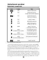
Page 29: ... keypad lets you control extra command features until you press any top row button like SW ACC RTE TR or ENG RailSounds sound system effects in bold italic AUX1 1Raises the volume of the RailSounds sound system Sound volume increases 2StationSounds announcement See the table on page 25 3Starts up the RailSounds sound system 4Lowers the volume of the RailSounds sound system Sound volume decreases 5...

Page 30: ...tationSounds Car a unique ID Choose from any number between 1 and 99 Remember it is best to assign your StationSounds Car the same ID as the locomotive with which it is operating Set the StationSounds Car PGM RUN switch to PGM Refer to Figure 8 for the location of that switch Plug in your Command Base then place the StationSounds Car on the track Set your PowerMasters to CMD or set your traditiona...

Page 31: ...he bottom of the StationSounds Car from RUN to PGM Refer to Figure 8 on page 30 for the switch location STEP 2 Plug in your Command Base STEP 3 Place your StationSounds Car on the track then turn on power to the track STEP 4 Press ENG then input the StationSounds Car s ID Press SET STEP 5 Press ENG ID AUX1 6 for your StationSounds Car STEP 6 Turn off power to the track then wait ten seconds STEP 7...

Page 32: ...r O 27 gauge 6 12020 for FasTrack layouts so that the truck is centered directly above the magnet in the track Once the car is in place press UNCOUPLE on the track controller to activate the Remote Control or Uncoupling Track section releasing the coupler To uncouple the cars by hand slide the uncoupling tab back towards the car Coupling your Aluminum Passenger Cars Uncoupling mechanism trigger pl...

Page 33: ...f your StationSounds Passenger Car As illustrated in Figure 10 the switch is located near the speaker on the underside of the frame Slide this switch to the ON position to turn on the lights or to the OFF position to turn off the lights Switching the interior lights on and off PGM RUN ON OFF Light switch Figure 10 StationSounds Car Operating and Maintaining your Passenger Cars PGM RUN switch Volum...

Page 34: ...off continued Baggage and Combination Cars The light switch is located inside one of the sliding baggage doors mounted to the circuit board on the ceiling Refer to Figure 1 for the location and position of the switch TOP OF CAR ON OFF Figure 11 Baggage and Combination Car switch location ...

Page 35: ...igure 12 the light switch is located at the end of the car On the Coach and Observation Cars the switch is located directly above the door The switch on the Offset Vista Dome is located on the underside of the frame TOP OF CAR TOP OF CAR BOTTOM OF CAR BOTTOM OF CAR Offset Vista Dome Car Coach and Observation Cars OFF ON Figure 12 Switch locations ON OFF positions ...

Page 36: ...30 9134 300 Make sure that the replacement lamp is positioned flat against the light panel Refer to Figure 14 5 Reassemble the car by following these steps in reverse order On the baggage and combination cars be sure that the brass eyelets beneath the screw heads are in place below the metal frame as illustrated in Figure 15 Replacing the lamps During the course of normal operations it may become ...

Page 37: ...loor screws Do not remove Rear vestibule screws Do not remove Floor screws Do not remove Light panel Vestibule end cap Figure 16 Baggage and Combination Cars Operating and Maintaining your Passenger Cars Replacing the lamps continued ...

Page 38: ... the car and unplug the wire connector As illustrated in Figure 13 on page 36 be sure to pull on the white connector housing not the wires 3 Carefully slide the light panel out of the car far enough to expose the expired lamp 4 Gently pull the expired lamp straight out of the socket then replace it with Lionel part no 630 9134 300 Make sure that the replacement lamp is positioned flat against the ...

Page 39: ...crews Floor screws Do not remove Rear vestibule screws Do not remove Floor screws Do not remove Light panel Vestibule end cap Bulkhead Figure 17 Coach Operating and Maintaining your Passenger Cars Replacing the lamps continued ...

Page 40: ...ector is found towards the end of the car with the smaller windows As illustrated in Figure 13 on page 36 be sure to pull on the white connector housing not the wires 3 Carefully slide the light panel out of the opposite end of the car 4 Gently pull the expired lamp straight out of the socket then replace it with Lionel part no 630 9134 300 Make sure that the replacement lamp is positioned like th...

Page 41: ...o not remove Rear vestibule screws Floor screws Do not remove Vestibule end cap Vestibule end cap Light panel Figure 18 StationSounds Diner Operating and Maintaining your Passenger Cars Replacing the lamps continued Connector Wire connector inside ...

Page 42: ... the center of the frame near each truck These screws are also illustrated in Figure 19 on page 43 4 Lift the trucks and metal frame from the body Take care not to pull on the wires that are attached to the frame 5 Slide the interior out through the front end until you can access the lamp 6 Gently pull the expired lamp straight out of the socket then replace it with Lionel part no 630 9134 300 Mak...

Page 43: ...Floor screws Detailed interior bottom level Lift trucks and frame out after removing the end caps and the floor screws Figure 19 Offset Vista Dome Car Vestibule end cap Vestibule end cap Operating and Maintaining your Passenger Cars Replacing the lamps continued ...

Page 44: ...wire connector mounted to the light panel As illustrated in Figure 12 on page 36 be sure to pull on the white connector housing not the wires 3 Slide the light panel out of the car to expose the expired lamp Refer to Figure 20 on page 45 4 Gently pull the expired lamp straight out of the socket then replace it with Lionel part no 630 9134 300 Make sure that the replacement lamp is positioned flat ...

Page 45: ...th ground wire Do not remove Floor screw with ground wire Do not remove Floor screw Do not remove Bulkhead Light panel Vestibule end cap Figure 20 Observation Car Operating and Maintaining your Passenger Cars Replacing the lamps continued Roof nut ...

Page 46: ...5 remove the nut from the bottom of the rounded end of the car and pull away the rear door Use a pair of tweezers or a small pair of pliers to pull the lamp straight up and out of the socket If you need more room loosen the two end screws remove the three floor screws from the bottom of the car slide out the vestibule and bulkhead and lift away the truck and metal frame Replace the lamp then reass...

Page 47: ...Notes 47 ...
Page 48: ... from state to state Instructions for Obtaining Service If service for this Lionel L L C product is required bring the item along with your dated sales receipt and completed warranty information to the nearest Authorized Lionel Service Center Your nearest Lionel Service Center can be found by calling 1 800 4 Lionel or by accessing our Website at www lionel com If you prefer to send your product ba...

Reviews: