background image

Rev: 11.23.22

Page 4

CCD-0004307

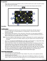
Preparation

1. 

Engine must be running, the park brake must be set, and the transmission in “park” (”neutral” for diesel 

coaches) for the jacks to operate.

2. 

Check leveling site to make sure obstructions have been cleared away for proper jack operation.

Operation

Leveling Coach

1. 

Turn on the ignition and start the coach. Your leveling control will start a self check sequence  

indicated by the lights on the panel blinking in a rotating pattern. It will turn off when it has  

finished its self check.

2. 

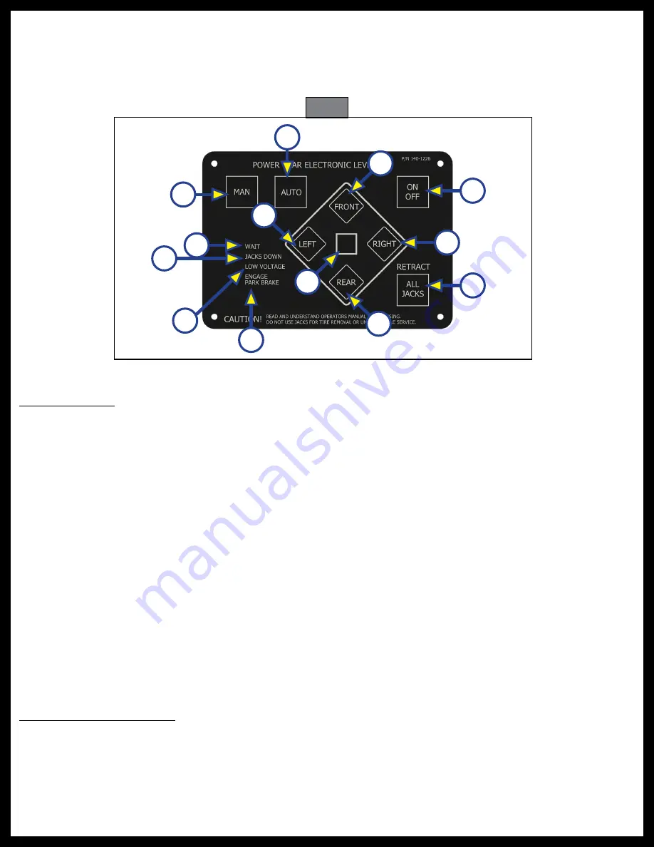
Push the ON/OFF (Fig.1A) button on the control panel. The system is now operational and ON/OFF 

(Fig.1A) LED will turn on. (On some controls, there will be a 10 second wait period before operation is 

allowed. During this time, the WAIT LIGHT (Fig. 1G) will flash.

Note:  

Check to see that the LOW VOLTAGE (Fig. 1L) light is not illuminated. If so, start the engine and wait 

a few minutes to ensure that the battery voltage is good. The engine must be running for the jacks 

to operate.

3. 

Check to see that the ENGAGE PARK BRAKE (Fig. 1M*) light is not illuminated. If so, engage the parking 

brake. (Your coach will have to be in neutral or park to operate the system.)

4. 

Push the AUTO (Fig.1C) button. The automatic leveling system will begin its leveling procedure. Please 

avoid movement in the coach during automatic leveling as it can cause errors in the results. It will 

signal that it has completed the process by illuminating the center green Power Gear LEVEL (Fig.1E) 

light. Check to make sure that all jacks are on the ground. Also check to make sure that no tire is off the 

ground. If so, your leveling process is complete. If further adjustments are needed, or one or more tires 

are off the ground, retract all jacks and refer to the “Manual Operation” section of this manual.

5. 

You can then turn the system off by pushing the ON/OFF (Fig.1A) button again.

Retracting Leveling Jacks

1. 

Turn on the ignition and start the coach.

2. 

Turn on the system by pushing the ON/OFF (Fig.1A) button. The system is now operational and the 

ON/OFF (Fig.1A) LED will turn on.

3. 

Push the RETRACT-ALL JACKS (Fig.1B) button. When the JACKS DOWN (Fig.1H) light turns off, visually 

check to make sure that all jacks have fully retracted. If so, your coach leveling system is ready to travel.

Fig. 1 

A

B

D

C

E

F

I

J

K

M

H

G

L

Summary of Contents for 140-1229

Page 1: ...Power Gear Automatic Leveling with Touch Pad 140 1229 OWNER S MANUAL 82 L0379 ...

Page 2: ... The Power Gear leveling system is designed as a leveling system only and should not be used to provide service for any reason under the coach such as changing tires or servicing the leveling system Note This information was obtained from Power Gear manual 82 L0379 Rev OE and manual updates dated April 2005 through May 2012 Owner s TSM Specific Additional information about this product can be obta...

Page 3: ... or other parts of the body near hydraulic leaks High pressure oil leaks may cut and penetrate the skin causing serious injury The CAUTION symbol above is a sign that a safety risk is involved and may cause personal injury and or product or property damage if not safely adhered to and within the parameters set forth in this manual Safety Read and understand all instructions before installing or op...

Page 4: ... light is not illuminated If so engage the parking brake Your coach will have to be in neutral or park to operate the system 4 Push the AUTO Fig 1C button The automatic leveling system will begin its leveling procedure Please avoid movement in the coach during automatic leveling as it can cause errors in the results It will signal that it has completed the process by illuminating the center green ...

Page 5: ...and rear lights are dark Note The right and left rear jacks are used to level the coach side to side Pushing the LEFT Fig 1 button on the control panel will extend the left rear jack Pushing the RIGHT Fig 1 button on the control will extend the right rear jack 7 Level the coach from side to side by pushing the RIGHT Fig 1 button if the light beside the RIGHT Fig 1 button is illuminated If the ligh...

Page 6: ...dures 2 4 until the weight of the coach is transferred off the jacks and onto the suspension and tires 6 This procedure will retract the front legs Using a 7 16 socket attached to a drill spin the override nut clockwise while holding the button on the FRONT LEG VALVE Fig 2B Stop when the legs are fully retracted 7 This procedure will retract the roadside rear leg After the front legs are retracted...

Page 7: ...ays with a silicone lubricant 7 Grease the fitting on the bottom of each jack cylinder with Lithium grease every 20 30 uses 8 Do not use a high pressured wash rinse system on of the components associated with the leveling system This includes the pump pump motor wiring harness control and touchpad The use of a high pressure wash rinse system will void the warranty Hydraulic Fluid Recommendation Th...

Page 8: ...es some time to charge The engine must be running for the jacks to operate Jacks will not extend or are extending slowly pump is running Fluid level low Fill tank to proper level with automatic transmission fluid see tip sheet 140 Batteries are weak Turn on the ignition and start the coach Wait a few minutes to allow the batteries some time to charge The engine must be running for the jacks to ope...

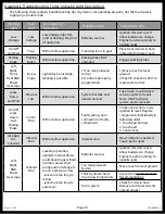
Page 9: ... level if manual mode is used Left Right Front Rear AND Power Gear logo Diagnostic Check For approximately five seconds the Front Right Rear and Left lights flash in a clockwise pattern along with the Power Gear logo Normal operational diagnostic check activated when ignition is turned ON Control will turn off after diagnostic check or a trouble code will flash All lights flashing Emergency Retrac...

Page 10: ...ogram control Jacks Down and Wait Pressure Loss Will not allow operation System has leak and needs serviced Take coach to authorized service center for repair Note ONLY hydraulic system needs serviced On Off Jacks Down and Parking Brake Comm Error Will not allow operation Faulty wiring poor connection or faulty component Check connections Cycle ignition to reset Replace components individually in ...

Page 11: ...Rev 11 23 22 Page 11 CCD 0004307 Notes ...

Page 12: ...ve has been provided Any unauthorized use shall void any applicable warranty The information contained in this manual is subject to change without notice and at the sole discretion of Lippert Revised editions are available for free download from lippert com Please recycle all obsolete materials For all concerns or questions please contact Lippert Ph 432 LIPPERT 432 547 7378 Web lippert com Email c...

Reviews: