Rev: 11.29.18
Page 10
CCD-0001755
A
Fig. 18
Fig. 17
x
x
A
B
C
Fig. 16
A
B
C
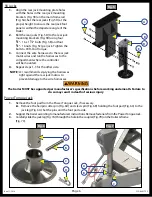
2.
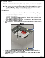
Attach the sensor (Fig. 16A) to the mounting plate (Fig. 16B) using two #12 - 14 x 1" hex head self-
drilling screws (Fig. 16C).
NOTE:
To avoid cracking the mounting sensor housing, do not over-tighten the screws.
3.
Attach the mounting plate and sensor assembly (Fig. 17B) to the cross-member (Fig. 17A) using two
#12 - 14 x 1" hex head self-drilling screws (Fig. 17C). Ensure that the plate is centered side to side on the
frame and that the sensor is oriented properly. See (Fig. 11 and Fig. 12) Sections A and B for location
clarification.
4.
Connect the sensor harness to the 3-Pin connector on the sensor (Fig. 18A) and run the harness
through the frame and up to the compartment where the controller will be mounted.

