Rev: 11.29.18
Page 11
CCD-0001755
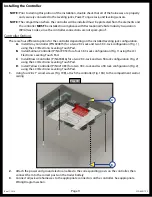
Fig. 19
A
B
Installing the Controller
NOTE:
Prior to starting this portion of the installation, double check that all of the harnesses are properly
and securely connected to the leveling jacks, Power Tongue Jack, and leveling sensors.
NOTE:
The compartment where the controller will be installed must be protected from the elements and
the controller
MUST
be installed in compliance with Recreational Vehicle Industry Association
(RVIA) Gas Codes, since the controller connections are not spark-proof.
Controller Options
There are four different options for the controller depending on the installed leveling jack configuration.
A.
Install Gray Controller (P/N 694815) for a two 2K C-Jack and two 3K C-Jack configuration (Fig. 1)
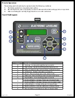
using the LCI Electronic Leveling Touch Pad.
B.
Install Salmon Controller (P/N 672953) for a four 3K C-Jack configuration (Fig. 1) using the LCI
Electronic Leveling Touch Pad.
C.
Install Brown Controller (P/N 694816) for a two 2K C-Jack and two 5K Jack configuration (Fig. 2)
using the LCI Electronic Leveling Touch Pad.
D.
Install Yellow Controller (P/N 421483) for a two 3K C-Jack and two 5K Jack configuration (Fig. 2)
using the LCI Electronic Leveling Touch Pad.
1.
Using four #8 x 1” wood screws (Fig. 19B), attach the controller (Fig. 19A) to the compartment wall or
ceiling.
2.
Attach the power and ground electrical cables to the corresponding posts on the controller, then
connect them to the correct posts on the trailer battery.
3.
Connect all jack wire harnesses to the appropriate connectors on the controller. See appropriate
Wiring Diagram section.

