background image

Rev: 11.29.18

Page 5

CCD-0001755

Installation

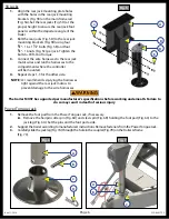
Fig. 3 

A

B

C

NOTE: 

Before checking ground clearance, make sure the trailer is parallel to the plain of the ground and 

level front to back.

For the 2K and 3K C-jack Leveling System, follow steps 1-4 for the front and the rear jacks. If installing 5K 

Jacks in the rear follow the 5K Jacks section.

NOTE: 

The height specifications for the C-jack Leveling System is a minimum of 10.5" and maximum 15" 

(measured from the bottom of the foot pad to the ground).

2K and 3K C-Jack

NOTE: 

Figure 3 depicts C-jacks installed onto an OEM cross-member.

1. 

Align the jack assembly mounting holes with the holes on the mounting bracket assembly across the 

chassis road-side to curb-side. 

2. 

Insert six  

3/8

" - 16 x 1 

1/2

" bolts (Fig. 3A) through each set of aligned mounting holes. 

3. 

Secure the bolts with a 

3/8

" - 16 nut (Fig 3B).

NOTE: 

Figure 4 illustrates the 

3/8

" - 16 x 1 

1/2

" bolt (Fig. 4A) within the C-channel of the mounting bracket 

assembly.

4. 

Connect the wire harnesses to the C-jack motor wires (Fig. 3C).  

Run the harnesses to the compartment where the controller will be 

mounted.  

NOTE: 

LCI recommends zip tying the wire harnesses tight against the front 

C-Jack motors to prevent damage to the wire harnesses.

Fig. 4 

A

The trailer MUST be supported per manufacturer's specifications before working underneath. Failure to 

do so may result in death of serious injury

Summary of Contents for Ground Control TT Leveling OneControl

Page 1: ...Rev 11 29 2018 Page 1 Ground Control TT Leveling with LCD Touch Pad OEM INSTALLATION MANUAL...

Page 2: ...ller Options 11 LCI Electronic Leveling Touch Pad 12 Prior to Operation 13 Touch Pad Diagram 13 Basic Jack Operation 14 System Settings 14 Homing Jacks 14 Zero Point Calibration 15 Operation 15 Unhitc...

Page 3: ...ch Panel is specific to travel trailer applications only Note The images in this manual are designed to illustrate the installation procedure only and may not represent the exact trailer being worked...

Page 4: ...to the lowest point on the front or rear of the trailer These string lines are shown as dotted lines Fig 1 and Fig 2 Note C Jacks shown for reference only to mark proper locations Ground Draw Bar App...

Page 5: ...the jack assembly mounting holes with the holes on the mounting bracket assembly across the chassis road side to curb side 2 Insert six 3 8 16 x 1 1 2 bolts Fig 3A through each set of aligned mounting...

Page 6: ...r will be mounted 4 Repeat steps 1 3 for the other side Note LCI recommends zip tying the harnesses tight against the rear jack motors to prevent damage to the wire harnesses A B C D Power Tongue Jack...

Page 7: ...Tongue Jack to a 30 amp fuse then to a grounded 12V power supply on the trailer Note The Power Tongue Jack has an option to replace the foot pad or attach the Drop Leg foot pad 8 Reattach the foot pa...

Page 8: ...ed in front of the front leveling jacks The rear sensor must be in line with or behind the rear leveling jacks as signified by Section B in Fig 11 and Fig 12 Both the front sensor and the rear sensor...

Page 9: ...for both sensor installations Note Leveling sensor mounting plate might be pre installed by LCI if so perform step 2 and step 4 1 Dry fit the mounting plate Fig 15C and the leveling sensor Fig 15B to...

Page 10: ...h the mounting plate and sensor assembly Fig 17B to the cross member Fig 17A using two 12 14 x 1 hex head self drilling screws Fig 17C Ensure that the plate is centered side to side on the frame and t...

Page 11: ...5 for a two 2K C Jack and two 3K C Jack configuration Fig 1 using the LCI Electronic Leveling Touch Pad B Install Salmon Controller P N 672953 for a four 3K C Jack configuration Fig 1 using the LCI El...

Page 12: ...Fig 21 so the top and bottom horizontal cuts are parallel to the floor of the compartment 4 Feed the touch pad harness through this hole and run it to the compartment where the controller is mounted P...

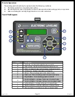
Page 13: ...Arrow Scrolls up through the menu on LCD B Down Arrow Scrolls down through the menu on LCD C Enter Activates modes and procedures indicated on LCD D LCD Display Displays procedures and results E Retr...

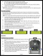
Page 14: ...Fig 24I or FRONT and RIGHT Fig 24J buttons Similarly the rear jacks can be retracted together by pushing the REAR button Fig 24K or individually by pushing the combination of the REAR and LEFT Fig 24I...

Page 15: ...he trailer is level turn off the touch pad 3 With the touch pad off press and release the FRONT button Fig 24H 5 times and then press and release the REAR button Fig 24K 5 times 4 The touch pad will f...

Page 16: ...the rear jacks are retracted B The Power Tongue Jack may adjust depending on the orientation of the trailer C Front jacks will extend until movement of the trailer is sensed D The Power Tongue Jack w...

Page 17: ...utton was most recently pressed 4 Press the ON OFF button to turn system off Fig 31B 5 Back the tow vehicle into position to align the tow vehicle hitch and trailer coupler with each other 6 Press and...

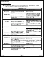
Page 18: ...tion of jacks Relocate the trailer Unexpected high amp current stall Check jacks in manual mode or perform manual override procedure Repair or replace as needed Check for bent or damaged jacks Repair...

Page 19: ...s begin to retract The jacks will retract until they reach the hard current limit 4 The jacks are now homed and the special jack error code will be cleared Note If the jacks do not retract an error sh...

Page 20: ...ck Note If the travel trailer is equipped with 4 C Jacks the override procedure is the same for the front and rear 2K or 3K C Jack Motor Override Tools needed 3 8 drive ratchet and extension no socket...

Page 21: ...o the port and onto the nut Fig 40A 4 Turn the override until the jack extends or retracts to desired position Fig 37 A Fig 39 Fig 38 Fig 40 Fig 36 A B Preventive Maintenance 1 For optimum performance...

Page 22: ...ery Front Jack Recommended 50 Amp Circuit Protection Per RVIA Standards OEM Supplied Rear Jack Harnesses Leveling Sensor LCD Touch Pad Rear Sensor Harness Touch Pad Harness Controller Front Jack Harne...

Page 23: ...tery Front Jack Recommended 50 Amp Circuit Protection Per RVIA Standards OEM Supplied Rear Jack Harnesses Leveling Sensor LCD Touch Pad Rear Sensor Harness Touch Pad Harness Controller Front Jack Harn...

Page 24: ...tery Front Jack Recommended 50 Amp Circuit Protection Per RVIA Standards OEM Supplied Rear Jack Harnesses Leveling Sensor LCD Touch Pad Rear Sensor Harness Touch Pad Harness Controller Front Jack Harn...

Page 25: ...tery Front Jack Recommended 50 Amp Circuit Protection Per RVIA Standards OEM Supplied Rear Jack Harnesses Leveling Sensor LCD Touch Pad Rear Sensor Harness Touch Pad Harness Controller Front Jack Harn...

Page 26: ...ive has been provided Any unauthorized use shall void any applicable warranty The information contained in this manual is subject to change without notice and at the sole discretion of LCI Revised edi...

Reviews: