6
432-LIPPERT (432-547-7378)
Rev:06.30.22
JT’s Strong Arm
™
Travel Trailer
Installation and Owner’s Manual
(For Aftermarket Applications)
CCD-002345
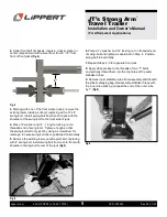
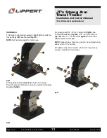
Fig.7
10.
Tighten “T”-bolts until snug. To ensure proper
installation, make sure the warning labels are facing
outward and right-side up. The T-bolts should also be on
the top side of the stabilizers.
11.
Repeat Steps 9 and 10 for opposite side.
12.
Fully retract the front scissor jacks.
13.
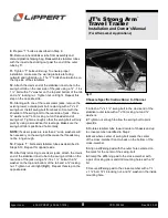
Attach the clevis end of the stabilizer inner tube to the
swing-bolt tab on the front side of the jack using a
3/8
” - 16 x 1 ½” bolt with a
3/8
” washer on the top and bottom
of the tab and a
3/8
” locking nut
(Fig.6)
. Tighten nut until
tight. Repeat this step on the opposite side.
14.
Insert a
3/8
” x 1 ¼” swing-bolt into a spacer mount and
secure with a
3/8
” washer and
3/8
” locking nut.
15.
Attach assembled spacer mount to clevis end of
the stabilizer outer tube using a
3/8
” - 16 x 1 ½” bolt and
a
3/8
” washer on both sides of the clevis Tighten
a
3/8
” locking nut enough to allow the stabilizer to swivel
by hand with some resistance. Repeat this step for the
opposite side
(Fig. 7)
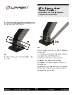
16.
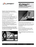
Swing the stabilizer toward the center of the chassis
and up to the cross-member identified in Step 2. Make
sure that the front of the spacer mount is parallel to front of
cross-member and the mounting holes are centered front-
to-back on the cross-member
(Fig.8)
.
17.
With the spacer mount held against the cross-member,
mark the mounting hole locations with a marker.
18.
Center punch each location. Drill a
1/8
” pilot hole at each
mounting hole location. Drill out one of the mounting holes
to
5/16
”and tap either using a
3/8
” - 16 tap or a
3/8
” - 16 x 1”
self-tapping bolt.
19.
Lubricate as needed.
20.
Remove tap or bolt and secure spacer mount with
a
3/8
”- 16 x 1” self-tapping bolt, taking care to keep the
remaining pilot hole centered in the mounting hole of the
spacer mount. Tighten bolt securely.
21.
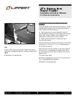
Drill remaining pilot hole to
5/16
” and insert a
3/8
”-16 x 1”
self-tapping bolt and tighten. Repeat this step for opposite
side
(Fig.8)
.
Fig.8

