14
432-LIPPERT (432-547-7378)
Rev: 08.29.22
Quick Drop Stabilizer
Installation and Owner’s Manual
(For Aftermarket Applications)
CCD-0004455
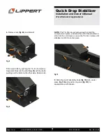
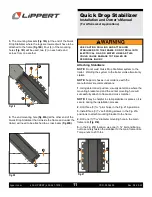
3.
The mounting brackets
(Fig. 25A)
(at the end of the Quick
Drop Stabilizer where the legs are lowered) will have to be
attached to the frame
(Fig. 25B)
. Four (4) of the mounting
holes
(Fig. 25C)
will be used, two (2) on each side and
across from one another.
4.
The end mounting hole
(Fig. 26A)
(at the other end of the
Quick Drop Stabilizer that is inside the frame and under the
trailer) will need to be attached to a cross beam
(Fig. 26B)
.
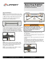
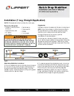
Attaching Stabilizers
NOTE:
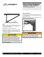
Do not weld Quick Drop Stabilizers system to the
trailer. Welding the system to the trailer voids all warranty
claims.
NOTE:
Support chassis in accordance with the
manufacturer’s recommendations.
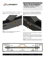
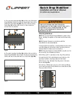
1.
Using determined position, visually determine where the
mounting bracket end and the center mounting hole will
actually attach to frame and cross member.
NOTE:
It may be helpful to clamp stabilizer is place so it is
secure during the installation process.
2.
Drill three (3)
5/16
" pilot holes in the Fig. 27A positions.
3.
Install three (3)
3/8
” self-drilling screws in the Fig. 27A
positions to attach mounting bracket to the frame.
4.
Drill one (1)
25/64
” diameter mounting hole in the main
frame rails
(Fig. 27B)
.
5.
In the Fig. 27B location, use one (1)
3/8
” bolt and flange
nut to securely fasten the stabilizer to the main frame rails.
Torque nuts to 23 ft-lbs.
Fig.25
A
C
C
C
C
B
Fig.26
A
B
A
A
B
Fig.27
USE CAUTION DRILLING AND ATTACHING
STABILIZERS TO THE FRAME. DO NOT DRILL INTO
ELECTRICAL, GAS, OR WATER LINES AS THIS
COULD CAUSE DAMAGE TO TRAILER OR
PERSONAL INJURY.
A

