background image

18

lippert.com 

    432-LIPPERT (432-547-7378)   


Rev: 08.29.22

Quick Drop Stabilizer

Installation and Owner’s Manual

(For Aftermarket Applications)

CCD-0004455

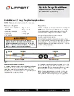
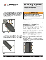
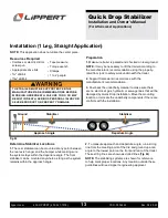
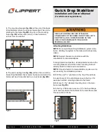
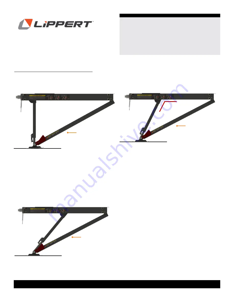
Examples of Quick Drop Stabilizer Positioning
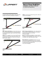
The following figures show examples of the Quick Drop 

Stabilizer from optimal to inadequate stabilization.

Fig.31 

Fig.32 

BEST: Optimal Stabilization

 is achieved when the inner 

arm and Quick Drop leg clear the visual gauge AND the 

inner arm and assembly body are almost at a 90 degree 

angle 

(Fig.31)

.

NOTE: 

Upon completion, the inner arm should not have 

moved beyond a 90 degree angle; perpendicular to the 

assembly body. Doing so may cause the mechanism to 

bind and cause damage.

GOOD: Adequate Stabilization

 can be achieved with the 

inner arm and assembly body greater than a 90 degree 

angle, BUT the inner arm is clear of the  

visual gauge 

(Fig. 32)

.

NOTE: 

The GOOD position 

(Fig. 32)

 is recommended for 

preloading so that the stabilizer can be extended and finish 

in the BEST position 

(Fig. 31)

 (90 degree angle).

BAD: Stabilization is inadequate 

when the inner arm 

and Quick Drop leg ARE NOT clear of the visual gauge. 

The angle of the inner arm and assembly body is too great 

to assure that the trailer weight can be  

evenly distributed 

(Fig. 33)

Best Positioning

Good Positioning

Fig.33 

Bad Positioning

NOTE: 

The black line represents the ground in relation to 

the Quick Drop Stabilizer.

Summary of Contents for 2022016064

Page 1: ...Piece 4 Resources Required 4 Preparation 4 Determine Stabilizer Locations 4 Measuring Frame and Adjusting Assembly Width 5 Attaching Stabilizers 9 Installation 1 Leg Angled Application 10 Resources R...

Page 2: ...ctively interfacing with the device product or system Failure to correctly follow the provided instructions may result in death serious personal injury severe product and or property damage including...

Page 3: ...A R spare 3 Double Leg Kit 2022016065 Double Leg Kit 2022016065 Letter Letter PN PN Description Description Qty Qty A 2021102390 Quick Drop Stabilizer 2 B 117919 Flange Bolt 3 8 16 x 1 2 C 118102 Sel...

Page 4: ...Torque wrench Clamps 1 to 2 people Installation 2 Legs Center Piece Resources Required THE TRAILER MUST BE SUPPORTED PER THE MANUFACTURER S RECOMMENDATIONS BEFORE WORKING UNDERNEATH FAILURE TO DO SO...

Page 5: ...e to the outside of the frame flange on the other side Fig 4A Fig 2 A width Web NOTE Most trailers will have J Wrap trim preventing the frame from being completely visible The Quick Drop Stabilizer MU...

Page 6: ...Needed measurement Fig 7 Mounting Bracket Mounting Bracket Flange to attach Flange to attach NOTE Figures 5 and 6 shown for reference for better clarity Web of frame Flange Mounting Bracket Quick Dro...

Page 7: ...ent Rod into the shaft Fig 9A with the bolts pushing out the bolts on the other side Retain bolts Fig 10 NOTE The T A R s are just wide enough to hold the components in place and allow the end of the...

Page 8: ...mounting to the frame 11 Repeat steps to attach other stabilizer to the opposite end of the center piece 12 Adjust legs in the center piece so the mounting holes desired on the mounting plate coincide...

Page 9: ...upside down as if the looking from the ground up underneath trailer Figure 16 shows Quick Drop Stabilizer from a horizontal view to provide clarity Mounting Plates Fig 14 Fig 15 4 Drill six 6 5 16 pil...

Page 10: ...TO DO SO MAY RESULT IN DEATH SERIOUS PERSONAL INJURY OR SEVERE PRODUCT OR PROPERTY DAMAGE Fig 18 Determine Stabilizer Locations 1 The rear stabilizer can be mounted at any point between the rear axle...

Page 11: ...rt chassis in accordance with the manufacturer s recommendations 1 Using determined position visually determine where the mounting bracket end and the center mounting hole will successfully attach to...

Page 12: ...16 pilot hole in the Fig 22A position 7 Install 1 4 self drilling screw through the mounting hole into the cross member Fig 22A 8 Repeat process if additional Quick Drop Stabilizer legs are being inst...

Page 13: ...LURE TO DO SO MAY RESULT IN DEATH SERIOUS PERSONAL INJURY OR SEVERE PRODUCT OR PROPERTY DAMAGE Fig 24 Determine Stabilizer Locations 1 The rear stabilizer can be mounted at any point between the rear...

Page 14: ...pport chassis in accordance with the manufacturer s recommendations 1 Using determined position visually determine where the mounting bracket end and the center mounting hole will actually attach to f...

Page 15: ...16 pilot hole in the Fig 28A position 7 Install 1 4 self drilling screw through the mounting hole into the cross member Fig 28A 8 Repeat process if additional Quick Drop Stabilizer legs are being inst...

Page 16: ...ck Drop Stabilizer Installation and Owner s Manual For Aftermarket Applications CCD 0004455 Additional Information Component Identification Hex Coupler Safety Chain Inner Arm Spring Latch Key Ring Qui...

Page 17: ...ick Drop Stabilizer is extending monitor the visual gauge as the outer arm drops and the inner arm moves across the assembly body toward the hex coupler The arms will need to be open enough Fig 30B fo...

Page 18: ...ndicular to the assembly body Doing so may cause the mechanism to bind and cause damage GOOD Adequate Stabilization can be achieved with the inner arm and assembly body greater than a 90 degree angle...

Page 19: ...LER COMPLETELY OFF THE GROUND LIFTING THE TRAILER COMPLETELY OFF THE GROUND CREATES AN UNSTABLE CONDITION THAT COULD RESULT IN PROPERTY DAMAGE AND PERSONAL INJURY 2 Using a 3 4 socket on a ratchet or...

Page 20: ...IZER LEGS HAVE BEEN EXTENDED DO NOT USE THE TONGUE JACK ON A TRAVEL TRAILER OR THE LANDING GEAR ON A 5TH WHEEL DAMAGE TO THE STABILIZER LEGS CAN OCCUR WHEN LIFTING OR LEVELING THE TRAILER AFTER THE ST...

Page 21: ...mpletely retract the Quick Drop leg Fig 39B into the inner arm for the next use Finish turning the hex coupler counterclockwise to completely retract the Quick Drop Stabilizer DO NOT OVER TIGHTEN THE...

Page 22: ...stress on system Use Quick Drop correctly to balance weight to not cause damage to stabilizers or trailer Replace part Maintenance It is recommended that when operating in harsh environments e g road...

Page 23: ...23 lippert com 432 LIPPERT 432 547 7378 Rev 08 29 22 Quick Drop Stabilizer Installation and Owner s Manual For Aftermarket Applications CCD 0004455 Notes...

Page 24: ...mplete document only unless Lippert provides explicit consent to distribute individual parts All manual information is subject to change without notice Revised editions will be available for free down...

Reviews: