10
432-LIPPERT (432-547-7378)
Rev: 08.29.22
Quick Drop Stabilizer
Installation and Owner’s Manual
(For Aftermarket Applications)
CCD-0004455
Preparation
1.
Make sure trailer is parked and chocked on level ground.
NOTE:
It may be necessary to lift the trailer according to
the manufacturer’s recommendation using the properly-
rated floor jack to safely work underneath the trailer.
2.
Support framework in accordance with the
manufacturer’s recommendation.
3.
Peel back the underbelly material to make sure there
are no electrical, gas, hydraulic or sewage lines that will be
damaged by Quick Drop installation. Move the mounting
location or relocate the underbelly components if there are
conflicts with the installation.
Installation (1 Leg, Angled Application)
THE TRAILER MUST BE SUPPORTED PER THE
MANUFACTURER'S RECOMMENDATIONS BEFORE
WORKING UNDERNEATH. FAILURE TO DO SO MAY
RESULT IN DEATH, SERIOUS PERSONAL INJURY OR
SEVERE PRODUCT OR PROPERTY DAMAGE.
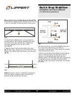
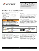
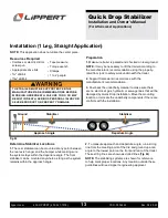
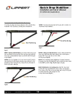
Fig.18
Determine Stabilizer Locations
1.
The rear stabilizer can be mounted at any point between
the rear axle hanger and the bumper while making sure
the system stays within the departure angle. The front
stabilizer can be mounted anywhere as long as the system
remains within the approach angle.
Stabilizer
Stabilizer
Ground
Approach Angle
Departure Angle
2.
To measure approach and departure angle, run a string
line from the meeting point of the tire and ground up at an
angle to the lowest point on the front and rear of the trailer.
These string lines are shown as dotted lines
(Fig. 18)
.
NOTE:
The stabilizing systems are shown for reference
only to help mark proper locations. Any location outside
these guidelines will need Lippert engineering approval.
NOTE:
This application does not utilize the center piece.
Resources Required
• Cordless or electric drill or
screw gun
• Appropriate drive bits
•
5/16
" drill bit
•
25/64
" drill bit
• Tape measure
• Torque wrench
• Clamps
• 1 to 2 people

