background image

Rev: 06.30.22

Page 8

CCD-0001575

Automatic Upper Bunk Lock-Up System Option

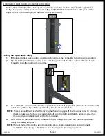
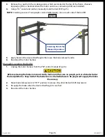
Each of the lower trolleys has a lock-up mechanism attached. This mechanism pushes the upper bunk 

trolleys into spring-backed bunk lock assembly (Fig. 10A) bolted into the C-channels. This prevents the 

upper trolleys from lowering when the lower trolleys are lowered. 

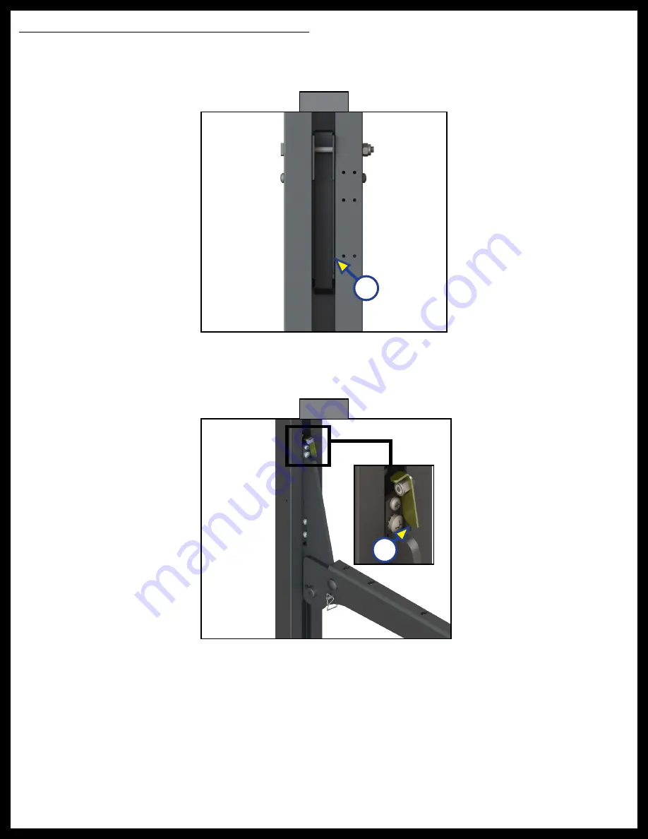
Fig. 11 

A

Locking the Upper Bunk Trolleys

1. 

If the lower trolleys have a sofa or dinette attached, rotate the seatback(s) to the horizontal position. 

2. 

Flip the locking mechanism tab (Fig. 11A) so the long portion of the tab is outside of the C-channel. 

Repeat for the other locking mechanisms.

A

Fig. 10 

3. 

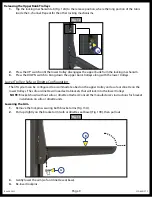
Press UP on the control switch until the upper bunk is in the full up position where the bed lift shuts off 

automatically. This will push the upper trolleys into the locking brackets.

NOTE: 

 There is an audible click when the locking mechanism engages. If the mechanism fails to latch up, 

check to make sure the bunk lock assembly bolt is not too tight and that the bunk lock assembly 

mechanism springs back freely within the C-channel..

4. 

Press DOWN on the control switch to lower the lower trolleys and make sure that the upper bunk 

trolleys are locked into place. 

NOTE: 

If one or more of the trolleys is not locked into place, check all alignments and component 

installations. See Timing in Adjustments for checking and correcting alignment. 

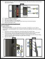
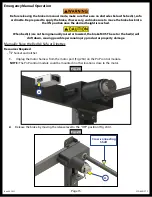
Summary of Contents for HAPPIJAC

Page 1: ...HappiJac Bed Lift OWNER S MANUAL...

Page 2: ...12V DC Nominal Current Draw 8 amps 1 bed going up 12 amps 2 beds or 1 bed and 1 sofa dinette configuration going up Load Limit 450 pounds dynamic moving load 600 pounds static stationary load Note Th...

Page 3: ...t out instructions for every possibility but provides the general instructions as necessary for effectively interfacing with the device product or system Failure to correctly follow the provided instr...

Page 4: ...ig 1A Each c channel rail encases a chain drive and trolleys Fig 2 with attached brackets that travel between upper and lower limit switches Fig 1 Fig 2 Upper Trolley A Standard Lower Trolley Slotted...

Page 5: ...ll screws Fig 6B The limit switches are used to stop the bed s at their maximum travel range However the lower bed platform can be stopped and used at any desired height After the control switch is re...

Page 6: ...s above below and adjacent to the bed s are free from obstructions before operating the bed s ALWAYS check before operating bed s to ensure that there is nothing interfering with the travel of the cha...

Page 7: ...ed platform rails Fig 9A are secured to the tab brackets Fig 9B and the bed platform rests on the platform rails Fig 8 A B Note Bed platform has been removed for clarity The upper trolleys can be lock...

Page 8: ...Repeat for the other locking mechanisms A Fig 10 3 Press UP on the control switch until the upper bunk is in the full up position where the bed lift shuts off automatically This will push the upper tr...

Page 9: ...B Fig 12 Lower Trolley Sofa or Dinette Configuration The lift system can be configured to accommodate a bed on the upper trolley and a sofa or dinette on the lower trolleys The sofa or dinette will n...

Page 10: ...em should be set 1 4 to 1 2 higher than the motor side To adjust the timing 1 Press the DOWN switch to lower the bedlift system until it stops 2 Measure from the bottom of the lower trolley sofa brack...

Page 11: ...A Remove the hairpin Fig 18A securing the clevis pin Fig 18B and washer Fig 18C B Remove the clevis pin holding the bedlift rail Fig 18D to the tab bracket Fig 18E C Repeat for the other side 3 Carefu...

Page 12: ...river The sofa dinette brackets can be removed from the lower trolleys and trolley tabs can be added to accommodate a second bed platform See Lower Bunk Trolley Tab Installation for instructions on ad...

Page 13: ...racket can only be installed with the trolley tab at the top 1 Remove the sofa brackets from the lower travel trolley See Lower Trolley Sofa Dinette Bracket Removal 2 Line up the hooks on the edge of...

Page 14: ...tive limit switch Replace limit switch Faulty control module Replace module Faulty UP DOWN switch Replace switch Faulty brake Set manual brake release lever on motor to the OFF position If the bed s m...

Page 15: ...e the Bed s Sofa or Dinettes Resources Required 1 2 Socket and ratchet 1 Unplug the motor harness from the motor port Fig 23A on the PnP control module Note The PnP control module could be mounted in...

Page 16: ...pared to apply the brake if necessary 2 Move brake release lever to OFF position to release Fig 24A Bed will drift downward 3 Re apply the brake when the desired bed height is reached 4 Reconnect the...

Page 17: ...Rev 06 30 22 Page 17 CCD 0001575 Notes...

Page 18: ...e has been provided Any unauthorized use shall void any applicable warranty The information contained in this manual is subject to change without notice and at the sole discretion of LCI Revised editi...

Reviews: