TME-EPIC-HURQM-R2V1.docx
Revision 2.1
Page 18 of 52
•
Digital output (16/20/24-bit S/PDIF-out support 44,1k/48k/96/192kHz sampling rate)
o
S/PDIF
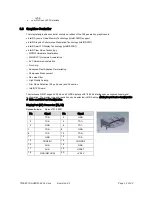
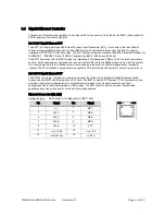
Audio Connector (X10)
Connector type:
IDC16 pin header 2.00 mm
Adapter cable:
available, part.no. 862-0065-10
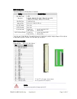
Pin
Signal
Pin
Signal
1
Line-Out R
2
Line-Out L
3
Surrond R
4
Surrond L
5
LFE
6
Center
7
GND-Audio
8
GND-Audio
9
Line-In R
10
Line-In L
11
Mic R
12
Mic L
13
GND
14
GND
15
S/P-Dif IN
16
S/P-Dif OUT
3.8
PCI/104-Express Bus Interface
The PCI Express architecture uses familiar software and configuration interfaces of the conventional PCI bus
architecture, but provides a new high-performance physical interface while retaining software compatibility with
the existing conventional PCI infrastructure.
PCI Express is a high performance I/O architecture used in both desktop and mobile applications. This
hierarchical, point-to-point interconnect works well with on-board and slot oriented architectures. The purpose of
this Specification is to adapt PCI Express to the stacked architecture employed with 104, EPIC and EBX form
factor.
PCI/104-Express have the following features:
•
Four x1 PCIe Lanes or one x4 PCIe Lane
•
One x16 PCIe or optionally two x8 PCIe
•
ATX power and control signals: +5V Standby, Power supply on, Power OK
•
Power: +3.3V, +5V, +12V
•
SMBus
Note:
The 3.3V pins on the PCI/104-Express bus are not supplied by the onboard
3.3V power supply in default. The maximum current is limited to 3.6 A. With
0R0-Resistor-Jumpers the 3.3V pins can by supplied by the onboard 3.3V
power supply, but with a lower current limit.
If a PCI/104-Express peripheral board needs 3.3V supply from the bus with
more than that limit, it must be supplied externally.

