TME-EPIC-HURQM-R2V1.docx
Revision 2.1
Page 27 of 52
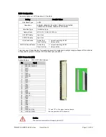
Power-LED
To see the Power activation, the signal "Power LED" must be pulled to +3.3V.
Pin
Signal
Pin
Signal
1
SMB_CLK
2
SMB_DATA
3
Power Button
4
GND
5
Reset Button
6
GND
7
HDD LED
8
+3.3V
9
Watchdog
10
+3.3V
11
Power LED
12
+3.3V
13
GPIO
14
GPIO
15
GPIO
16
GPIO
17
GPIO
18
GPIO
19
GPIO
20
GPIO
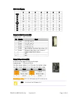
GPIO’s
Pin
Signal
Pin
Signal
1
SMB_CLK
2
SMB_DATA
3
Power Button
4
GND
5
Reset Button
6
GND
7
HDD LED
8
+3.3V
9
Watchdog
10
+3.3V
11
Power LED
12
+3.3V
13
GPIO
14
GPIO
15
GPIO
16
GPIO
17
GPIO
18
GPIO
19
GPIO
20
GPIO
3.13
Backup BIOS
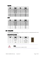
In order to recover from BIOS problems, a recovery BIOS can be used. This is a special hardware unit that can be
attached to the Backup BIOS Connector.
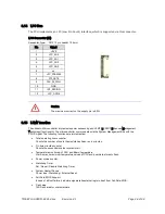
Backup BIOS Connector (X24)
Connector Type: IDC10 pin header 2.00 mm
Caution
The maximum current on the supply pin is 0.3A!
Pin
Signal
Pin
Signal
1
SPI_HOLD#1
2
SPI_CE#1_B
3
SPI_CE#0_B
4
+3V3
5
SPI_SO
6
SPI_HOLD#0
7
n.c.
8
SPI_CLK_B
9
GND
10
SPI_SI_B

