TME-EPIC-HURQM-R2V1.docx
Revision 2.1
ii
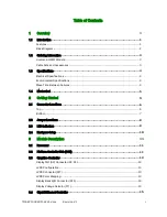
Ethernet Connector (X8, X29)
.......................................................................... 15
3.5
USB 2.0 Ports
............................................................................................ 16
USB Connectors (0-3 & 8-9, exemplary described USB 0/1, X12, X13, X14)
................. 16
USB Connectors (4-7, exemplary described USB 4/5, X28, X31)
............................... 16
3.6
Serial ATA Ports
.......................................................................................... 17
SATA Connector (X15, X16, X17, X19)
............................................................... 17
3.7
Audio
....................................................................................................... 17
Audio Connector (X10)
.................................................................................. 18
3.8
PCI/104-Express Bus Interface
........................................................................ 18
PCI/104-Express Connector (X18)
.................................................................... 19
3.9
PC/104-Plus Bus Interface
............................................................................. 21
PC/104-Plus Connector (X32)
......................................................................... 22
3.10
PCIe Mini-Card (X9)
..................................................................................... 23
3.11
On Board Power Supply
................................................................................ 24
Power Connector (X26)
................................................................................. 24
Real Time Clock Backup
............................................................................... 24
3.12
System Panel Connector (X5)
.......................................................................... 25
SMBus/I²C
................................................................................................ 25
Power-Button
............................................................................................. 25
Reset-Button
............................................................................................. 26
HDD-LED
.................................................................................................. 26
Watchdog
................................................................................................. 26
Power-LED
................................................................................................ 27
GPIO’s
..................................................................................................... 27
3.13
Backup BIOS
............................................................................................. 27
Backup BIOS Connector (X24)
........................................................................ 27
3.14
LPC Bus
................................................................................................... 28
LPC Connector (X4)
..................................................................................... 28
3.15
LEMT function
............................................................................................ 28
3.16
CPU Fan Connector (X20)
.............................................................................. 29
3.17
Chassis Fan Supply (X21)
.............................................................................. 29
4
Using the Module
30
4.1
BIOS
........................................................................................................ 30


