Rev: 06.29.22
Page 10
CCD-0004431
D. Repeat steps 9A-C for the other cylinder.
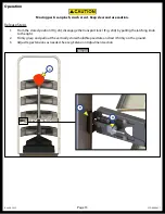
E. Deploy and lift the steps again to test. If there is too much resistance when lowering the step, the
nylock nut can be backed off slightly to decrease the resistance.
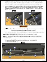
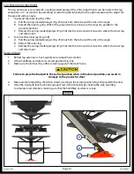
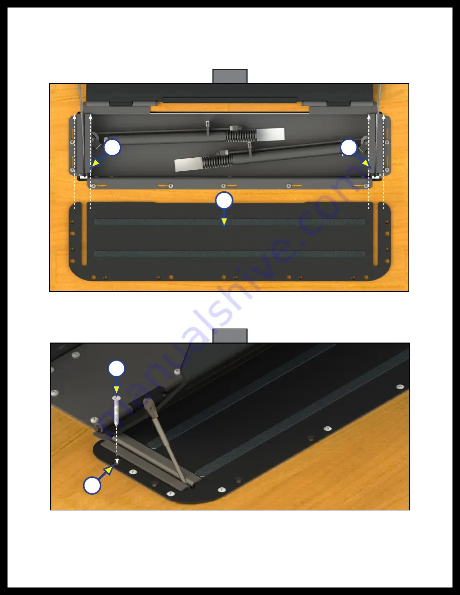
10. Slide the lift assist cover (Fig. 16A) around the cable guides (Fig. 16B) flush with the base profile
of the lift assist.
11. Install nine, #10 flat head screws (Fig. 17A) into the remaining pre-drilled holes on the cover through
the lift assist base and into the floor to secure.
Fig. 16
A
B
B
Fig. 17
A
B
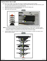
12. Remove the temporary pin or tool (Fig. 3A) that was installed prior to installation and secure the leg
extension in place with the spring loaded plunger (Fig. 3B).


