background image

Rev: 06.29.22

Page 8

CCD-0004431

3. 

Place the lift assist (Fig. 10A) inside the previously cut floor hole. Make sure the lift assist is aligned  

and flush with the side (Fig. 10B) and back of the hinge plate barrels (Fig. 10C) on both sides  

of the lift assist. 

Fig. 10 

4. 

Secure the lift assist to the floor using figure 11 as a guide as to which side the fasteners (Fig. 11A) 

should be installed in the precut fastener slots (Fig. 11B). 

Fig. 11 

A

B

C

C

5. 

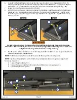
With a firm hold of the steps, carefully extend the steps to the ground. There are five pre-drilled holes 

along the side farthest away from the threshold plate (Fig. 12C) and one on each side. Install the 

five fasteners (Fig. 12B white box areas) along the inside of the lift assist that will go into the backer 

material (Fig. 9F) and one on each side (Fig. 12A). 

Fig. 12 

When moving the steps from the stored to extend and extend to stored positions, make sure you 

have a firm hold of the steps. Failure to keep control of the steps may cause damage  

to the doorframe or step assembly.

A

B

B

B

C

A

B

Summary of Contents for SolidStep Levitate

Page 1: ...SolidStep Levitate OEM INSTALLATION MANUAL...

Page 2: ...t provides the general instructions as necessary for effectively interfacing with the device product or system Failure to correctly follow the provided instructions may result in death serious persona...

Page 3: ...anyone other than a qualified professional The deployment and retraction of the step assembly can cause injury if proper precautions are not taken The step assembly was designed for an operational we...

Page 4: ...ted under one of the step extrusions typically the top full step SolidStep Levitate Assembly Steps Maximum to Minimum Floor Height Leg Height Double Standard Step 8 Rise 30 89 Maximum to 23 64 Minimum...

Page 5: ...alled before complete step installation A Remove the leg extension from the step by cutting the cable tie B Pull the spring loaded plunger Fig 3B and insert the leg extension into the receiver Do not...

Page 6: ...ate assembly is centered in the doorframe Fig 5 Door Frame Inner Flange Door Frame Inner Flange Measure Fig 5 Fig 6 A A B B 4 Carefully lift the step assembly into the upright stored position Fig 7 Th...

Page 7: ...fter the cut has been made Fig 9E underneath the floor frame out the sides of the area around the lift assist opening in the floor Fig 9F so that the screws for the inside side walls of the lift assis...

Page 8: ...Fig 11B Fig 11 A B C C 5 With a firm hold of the steps carefully extend the steps to the ground There are five pre drilled holes along the side farthest away from the threshold plate Fig 12C and one...

Page 9: ...the jam nut Fig 15C B Tighten the nylock nut Fig 15E no more that 2 full turns to increase resistance C Tighten the jam nut Fig 15C 6 Carefully lift the SolidStep Levitate steps into the stowed positi...

Page 10: ...de the lift assist cover Fig 16A around the cable guides Fig 16B flush with the base profile of the lift assist 11 Install nine 10 flat head screws Fig 17A into the remaining pre drilled holes on the...

Page 11: ...or frame If final adjustment is required loosen the two bolts Fig 19B and Fig 20B on either side of the adjustable latching mechanism for side to side adjustments Prior to using the transport lock the...

Page 12: ...has been adjusted test its functionality by shaking the step assembly to simulate road vibration 4 Engage and disengage the transport lock Fig 22C to ensure the transport latch flanges Figs 22A and 2...

Page 13: ...ase Steps 1 From the stored position Fig 24 disengage the transport lock l Fig 24A by pulling the latching knob to the right 2 Firmly grasp and pull out the vertically stored SolidStep Levitate and re...

Page 14: ...r leg Fig 25B A Pull the spring loaded plunger Fig 25A out from the tube and the slot in the angle B Retract the inner leg C Release the spring loaded plunger Fig 25A into the tube and slot closest to...

Page 15: ...ng the cover onto the battery pack 3 Install six AA batteries into the battery pack 4 Reinstall the cover and screws NOTE The motion sensor Fig 27A located in the threshold plate is a photo voltaic ce...

Page 16: ...ntative has been provided Any unauthorized use shall void any applicable warranty The information contained in this manual is subject to change without notice and at the sole discretion of LippertTM R...

Reviews: