Rev: 06.29.22
Page 9
CCD-0004431
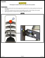
Do NOT attempt to adjust the tension when the SolidStep Levitate is in the extended position.
Should the cable have a fault, the tension stored in the springs at the extended position could cause
bodily harm or damage to the doorframe or step assembly.
9.
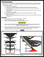
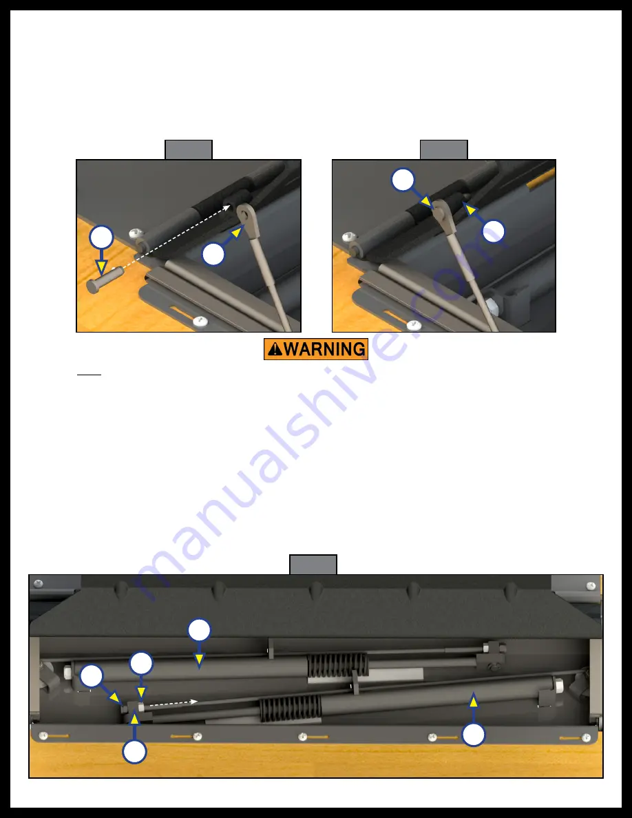
The lift assist uses two cylinder assist assemblies (Fig. A and B). Should the lift assist require adjustments,
follow the procedure as outlined below.
NOTE:
Perform adjustments from inside of the unit with the steps in the stored position.
NOTE:
The lift assist mechanism is set from the factory and typically does not require any adjustment.
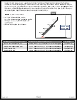
To increase resistance:
A. Loosen the jam nut (Fig. 15C).
B. Tighten the nylock nut (Fig. 15E) no more that 2 full turns to increase resistance.
C. Tighten the jam nut (Fig. 15C).
6.
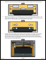
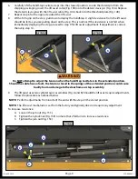
Carefully lift the SolidStep Levitate steps into the stowed position. Locate the detent pin from the
shipping packaging. Insert the lift assist cable (Fig. 13B) onto the detent clevis pin (Fig. 13A). Replace
the detent clevis pin with the lift assist cable (Fig. 14A), back into the threshold plate (Fig. 14B).
7.
Repeat step 6 for the opposite side of the lift assist
8.
With a firm grip on the step, pull down to deploy the SolidStep. A slight resistance from the lift assist
should be felt as you are pulling down on the step. This is normal. If this resistance is not felt when
immediately deploying the step, proceed to step 9 for lift assist adjustment. If adjustment is correct,
then skip step 10.
Fig. 15
C
A
D
B
E
Fig. 13
B
A
Fig. 14
A
B


