Rev: 06.29.22
Page 7
CCD-0004431
Lift Assist Installation for SolidStep Levitate Triple and Quad Step Assemblies
1.
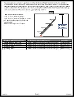
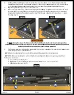
With a non-permanent method of marking, use a jig or template of the lift assist profile (Fig. 9A).
Mark where the floor should be cut for the lift assist to be placed down into the floor. The lift assist
profile has an alignment area that should be flush with the side (Fig. 9B) and back of the hinge plate
barrels (Fig. 9C). The dimension of the floor cut should be 25" X 5.75" (Fig. 9D, white box line).
2.
After the cut has been made (Fig. 9E), underneath the floor, frame out the sides of the area around the
lift assist opening in the floor (Fig. 9F) so that the screws for the inside side walls of the lift assist will
have a backer to go into.
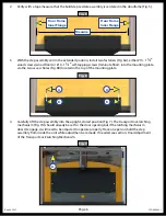
5.
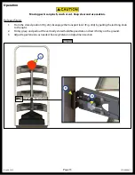
In the upright stored position, secure the hinge plate (Fig. 8A) to the floor of the trailer using fifteen
additional fasteners (Fig. 8B white box areas) in the pre-drilled holes of the hinge plate. Depending
on flooring material, use either #10 - 1 1/2" wood screws (wood floor) or #10 - 1 1/2" self-tapping
screws (laminate floor).
6.
Extend the step assembly and insert the plastic caps into the alignment cover holes on the mounting
plate (Fig. 8C).
Fig. 8
A
B
B
C
C
Fig. 9
A
E
B
C
B
C
25"
5.75"
F


