background image

9              

lippert.com 

    432-LIPPERT (432-547-7378)   

Rev: 06.15.22

SureShade

® 

Power 

Bimini Upgrades: Fly 

Extension

Installation and Owner’s Manual

(For Aftermarket Applications)

CCD-0004538

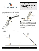
tie-down clip

saddle

Fig.19 

F. 

Attach the tie-down straps’ clips to the saddles 

(Fig.18)

.

G. 

Pull downward on each tie-down’s adjustment buckle 

until the fly extension is taut and does not sag.

D. 

Separate the loose saddles from the tie-down 

clips 

(Fig.19)

.

E. 

Align the saddles’ mounting holes with their previously 

marked (step C) locations, then install two 

1/4

”-10 x 

3/4

” 

Phillips head self-drilling screws 

(Fig.19A)


to secure 

the saddles.

 A

Reverse (rear) Fly Extension

When using a high speed mesh top, the fly extension 

can also be reversed, passing underneath the mesh 

top, to provide additional protection from undesirable 

weather conditions.
While the reversed fly extension position can be obtained 

with any Lippert bimini top with a zippered front pocket, its 

true benefit is best experienced in combination with a high 

speed mesh top.
The installation of the reversed fly extension position is 

performed in the same manner as outlined for the front, 

except the fabric is placed underneath the bimini top 

and secured to the rear rails with locking plates for the 

stanchions and saddles for the tie-down straps.

1. 

With the fly extension already installed and the bimini top 

frame and canopy fully extended

see Front Fly Extension 

procedure

unfasten the adjustable tie-down straps from 

their front-railing saddles and release the stanchions from 

their front-railing locking plates.

2. 

Walk the stanchions to the rear of the boat, passing the 

fly extension underneath the extended canopy.

3. 

Follow steps 17 and 18 of the Front Fly Extension 

section to install rear locking plates and tie-down strap 

saddles, except as follows:

A. 

Place the locking plates as far rearward on the top rails 

towards the rear of the boat without interfering with any 

obstructions, e.g., doors, furniture.

B. 

The stanchions should be positioned at a forward 

angle

towards the rear of the boat

so when the locking 

plates are installed a forward and downward tension will 

be applied to the fly extension.

Summary of Contents for SureShade Power Bimini 2021013744

Page 1: ...llation and Owner s Manual For Aftermarket Applications Bimini Extension Kits Bimini Extension Kits Part Part Description Description 2021013744 Bimini Extension Kit with Black Hardware 7ft with Black...

Page 2: ...ividual performing the instructions This manual cannot begin to plot out instructions for every possibility but provides the general instructions as necessary for effectively interfacing with the devi...

Page 3: ...k to the Lippert Store can be purchased 1 2 persons depending on task Cordless or electric drill or screw gun Appropriate drive bits Screwdriver Tape measure 1 8 hex wrench Non permanent marker A B C...

Page 4: ...ition Fig 2 Fig 1 Fig 2 7 Use an 1 8 hex wrench to loosen the setscrew Fig 3A in a jawslide remove the jaw screw Fig 3B then set the screw aside set tube to vertical aligned tube ends 8 Slip the jawsl...

Page 5: ...ake sure the two jawslides are aligned to one another 11 Separate the two halves of the tube then slip the front pocket of the extension fabric over the collared tube Fig 6 12 Reconnect the tube halve...

Page 6: ...te the stanchions A Position each swivel stud for insertion into the locking plate Fig 12 Fig 13 stanchion swivel stud locking plate B Place the locking plates Fig 13A as far forward on the top rails...

Page 7: ...and a non permanent marker to make sure each locking plate is located the same distance between 98 108 from the front of the actuator body Fig 14 NOTE Installing the slide base closer to 108 will pro...

Page 8: ...16 Fig 16 18 With stanchions locked in place at the front of the boat install adjustable tie down straps as follows Fig 17 A B boat railing Fig 18 A If necessary clip the adjustable buckle end of the...

Page 9: ...tion with a high speed mesh top The installation of the reversed fly extension position is performed in the same manner as outlined for the front except the fabric is placed underneath the bimini top...

Page 10: ...EDING MAXIMUM SPEED LIMIT WITH FLY EXTENSION DEPLOYED CAN CAUSE DAMAGE TO THE EXTENSION AND VOID PRODUCT WARRANTY Reverse rear Fly Extension With the bimini top fully opened and the fly extension moun...

Page 11: ...e fly extension fabric can be done as follows 1 If necessary remove the protective boot fully extend the bimini top and attach the fly extension to the front of the boat 2 If the top and extension was...

Page 12: ...uted as a complete document only unless Lippert provides explicit consent to distribute individual parts All manual information is subject to change without notice Revised editions will be available f...

Reviews: