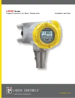
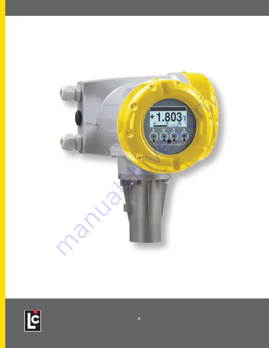
background image

1

WWW.LCMETER.COM

LCI40

 Series IOM

LCI40

®

 Series

Signal Converter for Mass Flowmeters

Installation and Parts

An IDEX Energy & Fuels Business

LC_LCRIIE26:V1-0716

L I Q U I D   C O N T R O L S

Summary of Contents for LCI40 Series

Page 1: ...1 WWW LCMETER COM LCI40 Series IOM LCI40 Series Signal Converter for Mass Flowmeters Installation and Parts An IDEX Energy Fuels Business LC_LCRIIE26 V1 0716 LIQUID CONTROLS...

Page 2: ...English versions of all Liquid Controls publications are available on our web site www lcmeter com It is the responsibility of the local distributor to provide the most current version of LC manuals i...

Page 3: ...g Sensor 16 4 6 Connecting Power All Housing VariantS 16 4 7 Inputs and Outputs Overview 17 4 8 Description of the Inputs and Outputs 21 4 electrical connections 4 9 Electrical Connection of the Input...

Page 4: ...lt repair with no effect on operation e g spelling mistakes on display 2 _ Downwards compatible hardware and or software change of interfaces P PROFIBUS F Foundation Fieldbus M Modbus X all interfaces...

Page 5: ...mperature as well to indirectly measure parameters such as the total volume and concentration of dissolved substances as well as the volume flow rate DANGER For devices used in hazardous areas additio...

Page 6: ...n salting out of product or separation of chemicals whether occurring during periods of use or storage 1 3 2 Product Liability and Warranty The operator shall bear responsibility for the suitability o...

Page 7: ...ory component All internal pressures must be relieved and all liquid drained from the system in accordance with all applicable procedures Pressure must be 0 zero psi Close all liquid and vapor lines b...

Page 8: ...local office of the manufacturer Information Do a check of the packing list to make sure that you have all the elements given in the order Information Look at the device nameplate to ensure that the d...

Page 9: ...ces as well as the volume flow rate Your measuring device is supplied ready for operation The factory settings for the operating data have been made in accordance with your order specifications Device...

Page 10: ...r terminal compartment 4 Cable entry for measuring sensor signal cable 5 Cable entry for measuring sensor field current cable 6 Cable entry for power supply 7 Cable entry for inputs and outputs 8 Moun...

Page 11: ...or the correct supply voltage printed on the nameplate 2 4 2 Electrical Connection Data of Inputs Outputs Example of Basic Version A active mode the signal converter supplies the power for connection...

Page 12: ...require adequate cooling e g by fan or heat exchanger Do not expose the signal converter to intense vibrations The measuring devices are tested for a vibration level in accordance with IEC 68 2 64 In...

Page 13: ...nce with the applicable occupational health and safety directives 3 6 2 Wall Mounting 3 6 1 Pipe Mounting Pipe Mounting of the Field Housing 1 Fix the signal converter to the pipe 2 Fasten the signal...

Page 14: ...d right of the display 3 Pull out the display between the two metal puller devices and rotate it to the required position 4 Slide the display and then the metal puller devices back into the housing 5...

Page 15: ...h line voltages up to 1000 V or equivalent national regulations CAUTION Use suitable cable entries for the various electrical cables The measuring sensor and signal converter have been configured toge...

Page 16: ...Connection Terminal Cable Pair Color 1 yellow X1 SA 1 black X1 SA 2 green X1 SB 2 black X1 SB 3 blue X2 T1 3 black X2 T2 4 red X2 T3 4 black X2 T4 5 white X3 DR 5 black X3 DR Connection of Signal Cabl...

Page 17: ...t shielding to spring terminal drain wire and overall shield DANGER The device must be grounded in accordance with regulations in order to protect personnel against electric shocks Cable Cable Connect...

Page 18: ...of a functional grounding conductor FE In hazardous areas grounding is used at the same time for equipotential bonding Additional grounding instructions are provided in the separate Ex documentation w...

Page 19: ...lerance range Power Supply Connection 1 100 to230 VAC 15 10 22 VA 2 24 VDC 55 30 12 W 3 24 VAC DC AC 15 10 DC 25 30 22 VA or 12 W 4 6 Connecting Power All Housing Variants 4 7 1 Combinations of the In...

Page 20: ...refer to the examples CG Number Examples CG 330 11 100 100 to 230 VAC standard display basic I O Ia or Ip Sp Cp Sp Pp Sp CG 330 11 7FK 100 to 230 VAC standard display modular I O Ia PN SN and optiona...

Page 21: ...A A B B C C D D Basic I Os standard 1 0 0 Ip 1 Sp Cp passive 2 Sp passive Pp Sp passive 2 Ia 1 PROFIBUS PA Ex i option D 0 0 PA PA PA PA FISCO Device FISCO Device D 1 0 Ia active PN SN Cp passive 2 PA...

Page 22: ...B Ip Pa Sa active 1 6 _ _ max 2 optional modules for term A B Ia Pp Sp passive 1 B _ _ max 2 optional modules for term A B Ip Pp Sp passive 1 PROFIBUS PA option D _ _ max 2 optional modules for term A...

Page 23: ...ted from each other and from all other circuits All operating data and functions can be adjusted Passive mode external power Uext 32 VDC at I 22 mA Active mode load impedance RL 1 k at I 22 mA RL 450...

Page 24: ...uty factor 1 1 independent of output frequency Automatic with fixed pulse width duty factor approx 1 1 at Q100 or Fixed pulse width adjustable as required from 0 05 ms to 2 s Forward reverse flow meas...

Page 25: ...re electrically isolated from each other and from all other circuits All operating data and functions can be adjusted Passive mode external power supply required Uext 32 VDC Active mode use of the int...

Page 26: ...ffects from electrical interferences EMC Terminal Compartment for Inputs and Outputs in Field Housing 1 Open the housing cover 2 Push the prepared cable through the cable entry and connect the necessa...

Page 27: ...puts must be connected passively or actively Which I O version and inputs outputs are installed in your signal converter are indicated on the sticker in the cover of the terminal compartment DANGER Fo...

Page 28: ...I 10 mA U0 max 2 V at I 100 mA fmax in operating menu set to 100 Hz fmax 10 kHz I 20 mA Open I 0 05 mA at Uext 32 VDC Closed U0 max 1 5 V at I 1 mA U0 max 2 5 V at I 10 mA U0 max 5 0 V at I 20 mA If...

Page 29: ...sive Basic I Os 8 V Uext 32 VDC Imax 6 5 mA at Uext 24 VDC Imax 8 2 mA at Uext 32 VDC Switching point for identifying contact open or closed Contact open off U0 2 5 V with Inom 0 4 mA Contact closed o...

Page 30: ...r the electrical connection of bus systems please refer to the separate documentation for the respective bus systems Current Output Active Modular I Os Uint nom 24 VDC I 22 mA RL 1 k X designates the...

Page 31: ...dance RL min is calculated as follows RL min U0 Imax X designates the connection terminals A B or D depending on the version of the signal converter Pulse Frequency Output Active Pa Pulse Frequency Ou...

Page 32: ...mA RL 47 k Open I 0 05 mA Closed U0 nom 24 V at I 20 mA X designates the connection terminals A B or D depending on the version of the signal converter Status Output Limit Switch Passive Modular I Os...

Page 33: ...with Inom 1 9mA Contact closed on U0 3V with Inom 1 9mA X designates the connection terminals A or B depending on the version of the signal converter Control input Passive Cp 1 Signal Control Input A...

Page 34: ...housing versions Shield connected via the cable terminals in the terminal compartment Any connection polarity Current Output Passive Ex i I Os Any connection polarity Uext 32 VDC I 22 mA U0 4 V RL Ue...

Page 35: ...ces used in hazardous areas additional safety notes apply Control Input Passive Cp Ex i 1 Signal Control Input Passive Ex i I Os 5 5 V Uext 32 VDC Imax 6 mA at Uext 24 V Imax 6 5 mA at Uext 32 V Switc...

Page 36: ...gnal Converter The measuring device consisting of the measuring sensor and the signal converter is supplied ready for operation All operating data have been set at the factory in accordance with your...

Page 37: ...Touching them from the side can cause incorrect operation After 5 minutes of inactivity there is an automatic return to measuring mode Previously changed data is not saved Display and Operating Eleme...

Page 38: ...move cursor highlighted in blue one position to the right Reset display Quick Access function Return to measuring mode but prompt whether the data should be saved Press 1 to 3 times return to menu mo...

Page 39: ...ndicates position within menu submenu or function list 5 Next menu submenu or function _ _ _ signalise in this line the end of the list 6 Current menu submenu or function 7 Previous menu submenu or fu...

Page 40: ...t value unit or function when selected appears with white text blue background This is where the data is changed 7 Current parameter 8 Factory setting of parameter Display When Previewing Parameters 4...

Page 41: ...ithout opening the housing IR Interface 1 Glass panel in front of the control and display panel 2 IR interface 3 LED lights up when IR interface is activated 4 Suction cups Timeout Function Following...

Page 42: ...ossible manual entry of zero calibration Storing the displayed zero calibration 5 x Save Configuration Yes Display Page Following installation perform zero calibration prior to commissioning the devic...

Page 43: ...edium Possible Solutions Media That Tend To Evaporate Or Outgas Increase pressure Two Phase Media Slurries That Contain Solids That May Fall Out Only fill the measuring sensor with the carrier medium...

Page 44: ...uage A2 Tag A3 Reset A3 1 Reset Errors A3 2 All Totalizers A3 3 Totalizer 1 A3 4 Totalizer 2 A3 5 Totalizer 3 A4 Analogue Outputs A4 1 Measurement A4 2 Unit A4 3 Range A4 4 Low Flow Cutoff A4 5 Time C...

Page 45: ...s Output X B1 _ Control Input X B1 _ Pulse Output X B2 Actual Values B2 1 Operating Hours Date and Time B2 3 Mass Flow B2 4 Volume Flow B2 5 Velocity B2 6 Density B2 7 Temperature B2 8 Strain 1 B2 9 S...

Page 46: ...sity Calib C1 9 Simulation C2 Concentration C3 I O Inputs Outputs C3 1 Hardware C3 _ Current Output X C3 _ Frequency Output X C3 _ Pulse Output X C3 _ Status Output X C3 _ Limit Switch X C3 _ Control...

Page 47: ...ge A1 Language Language selection depends on the device version A2 Tag A2 Tag Measuring point identifier Tag no appears in the LCD header maximum 8 digits A3 Reset A3 Reset A3 1 Reset Errors Reset Err...

Page 48: ...sets output value to 0 Setting x xxx x xxx range 0 0 20 1st value switching point 2nd value hysteresis condition 2nd value 1st value 2 Use for all outputs Make setting see Fct A5 1 above A6 GDC IR in...

Page 49: ...X B1 _ Frequency Output X B1 _ Control Input X B1 _ Limit Switch X B1 _ Status Output X B2 Actual Values B2 Actual Values Display of actual values Exit the displayed function with the key B2 1 Operat...

Page 50: ...ting Automatic Factory Settings Manual display last value set new value range 10 10 Break return with key C1 1 2 Zero Add Offset Direct setting of zero offset C1 1 3 Pipe Diameter Set the pipe diamete...

Page 51: ...1 4 1 Function Set the system control Select Inactive off Flow 0 flow to zero C1 4 2 Sys Ctrl Condition Set the condition for activating the system control Selection density or temperature C1 4 3 Sys...

Page 52: ...Nominal mass flow of measuring sensor C1 6 4 Max Allowed Temp Displays the maximum permitted temperature for the measuring sensor C1 6 5 Min Allowed Temp Displays the minimum permitted temperature fo...

Page 53: ...ndition 0 mA 1st value 2nd value 20 mA C3 _ 2 Extended Range Min and max limits of current values If the current range is exceeded the current is set to these limits xx x xx x mA range 03 5 21 5 mA Co...

Page 54: ...range only makes sense in combination with a status output External Range change by control input extended lower range control input must also be activated C3 _ 12 Threshold Appears only when Fct C3...

Page 55: ...ass flow 2 Conc volume flow 1 Conc volume flow 2 C3 _ 5 Range 0 to 100 of the measurement set in Fct C3 _ 4 x xx xx xx _ _ _ format and unit depend on the measurement see above C3 _ 6 Polarity Set pol...

Page 56: ...5 D C3 _ 1 Pulse Shape Specify the pulse shape Select Symmetric about 50 on and 50 off Automatic constant pulse with about 50 on and 50 off at 100 pulse rate Fixed fixed pulse rate setting see below...

Page 57: ...terminal A or D and only if output B is a pulse or frequency output If setting in Fct C2 5 6 is Both Polarities the phase shift is prefixed by a symbol e g 90 and 90 Select Off no phase shift 0 Phase...

Page 58: ...al output data see below Output C activated by the status of output Y additional output data see below Output D activated by the status of output Y additional output data see below Off switched off C3...

Page 59: ...6 Information Serial no of the I O board software version no and production date of the circuit board C3 _ 7 Simulation Sequence see B1 _ Limit Switch X C3 _ Control Input X C3 _ Control Input X C3 _...

Page 60: ...s C4 _ 5 Preset Value If this value is reached positive or negative a signal is generated that can be used for a status output at which Preset Totalizer X has to be set Preset Value max 8 digits x xx...

Page 61: ...V is tertiary variable C5 4 4V is 4th variable C5 _ 1 Current Output X Shows the current analogue measured value of the linked current output The measurement cannot be changed C5 _ 1 Frequency Output...

Page 62: ...mediately not just when setting mode is exited C6 2 3 Default Display Specification of the default display page that is returned to after a short delay period Select None the current page is always ac...

Page 63: ...lizer 3 Operating Hours Depending on the settings for the concentration measurement the following measurements are possible Concentration 1 Concentration 2 Conc mass flow 1 Conc mass flow 2 Conc volum...

Page 64: ...to menu Quick Setup without password xxxx password required range 4 digits 0001 9999 C6 6 5 Password Setup Password required to change data in the menu Setup 0000 to menu Quick Setup without password...

Page 65: ...text in the next two functions sequence see below C6 7 5 Text Free Unit For text to be specified refer to Set free units on page 87 C6 7 6 kg s Factor Specification of the conversion factor based on...

Page 66: ...etup Select Yes activated No switched off C6 9 3 Reset Totalizer 3 Reset Totalizer 3 in menu Quick Setup Select Yes activated No switched off C6 9 4 Reset All Totalizers Reset all Totalizer in menu Qu...

Page 67: ...hen release the key Language 2 x Reset Reset Errors All Totalizer Select desired Totalizer Totalizer 3 is optional Totalizer 1 Totalizer 2 Totalizer 3 Reset Totalizer No or Reset Totalizer Yes Totaliz...

Page 68: ...suring Setting the Operation Mode from measuring mode Key Display Description and setting A Quick Setup Press and hold for 2 5 s then release the key A9 Operation Mode Measuring Operation Mode Measuri...

Page 69: ...d point Factory Calibration The signal converter reactivates the factory settings for the density calibration Example of 1 point Calibration with Town Water Key Display Description and Setting A Quick...

Page 70: ...bration points did not pass the plausibility test Flow pressure temperature or system are not stable Please check your system and try again If this results in another failed calibration please contact...

Page 71: ...3 62 39112 999 3772 56 3 13 5 62 38708 999 3124 57 2 14 62 38284 999 2446 58 1 14 5 62 37841 999 1736 59 15 62 3738 999 0998 59 9 15 5 62 36901 999 0229 60 8 16 62 36403 998 9432 61 7 16 5 62 35887 99...

Page 72: ...1 76816 989 3986 117 5 47 5 61 75473 989 1835 118 4 48 61 7412 988 9668 119 3 48 5 61 72756 988 7484 120 2 49 61 71384 988 5285 121 1 49 5 61 70 988 3069 122 50 61 68608 988 0839 122 9 50 5 61 67205 9...

Page 73: ...77 7068 159 8 71 61 02074 977 4264 160 7 71 5 61 00316 977 145 161 6 72 60 98552 976 8624 162 5 72 5 60 96781 976 5786 163 4 73 60 95002 976 2937 164 3 73 5 60 93216 976 0076 165 2 74 60 91423 975 720...

Page 74: ...ositive as an increase in temperature usually reduces the measured density exception water anomaly Calculating The Standard Density The measuring device can display a density which has been corrected...

Page 75: ...diameter of the process pipe 6 5 8 Concentration measurement Menu C2 This menu is used to enter the password to activate concentration measurement in case the concentration option is purchased after...

Page 76: ...programmable period of time can be programmed in menu C1 3 2 the pressure suppression threshold is added to the standard low flow threshold can be set in menu C1 3 3 The optimal setting values for pr...

Page 77: ...om with e g 0 02 If the threshold is exceeded C3 4 2 a message is sent via terminals C Example Regarding The Detection And Notification Of A Two Phase Disturbed Flow e g Gas Bubbles In Paints Fct Disp...

Page 78: ...ored in a memory Backup 1 Saves settings in backup memory area 1 Backup 2 Saves settings in backup memory area 2 6 5 17 Load Settings Menu C6 6 3 This function allows the complete stored settings to b...

Page 79: ...an be used In this case perform the following settings C3 3 11 Phase shift to D or shift to A All functions for output B are set using output D or output A C3 5 11 Setting phase shift from output B re...

Page 80: ...sufficiently accurate and should be checked M Maintenance Required Measurements are still accurate but this could soon change C Function Check A test function is active The displayed or transferred m...

Page 81: ...old start If message reappears contact manufacturer System Error A System Error C HW Combination Error BM Failure DM Failure Process Input Failure IO 1 Failure IO 2 Failure Tot 1 Failure Tot 2 Failure...

Page 82: ...gs for IO1 Check settings for IO1 or load factory settings IO2 Configuration Inadmissible settings for IO2 Check settings for IO2 or load factory settings Tot 1 Configuration Inadmissible settings for...

Page 83: ...module is active and being used Check Fieldbus settings PROFIBUS Sim Man Active The simulation function in the PROFIBUS module isactive and being used Check PROFIBUS settings Totalizer 1 FB4 Sim Activ...

Page 84: ...s out of range The measurement continues but the accuracy of the density and flow is undetermined Check process conditions and density calibration Velocity Out of Range The flow is out of range The ac...

Page 85: ...at A Check current at A IO A Connection Open circuit or short circuit at IO A IO B Connection Current output B cannot provide the necessary current The current provided is too low The current at inpu...

Page 86: ...t zero Tot 2 Overflow Totalizer 2 has overflowed and started again at zero Tot 3 Overflow Totalizer 3 has overflowed and started again at zero I I Proc System Control System Control Active System cont...

Page 87: ...on values Tot 1 No Meas Values The measurement value for the Totalizer 1 is not active Select another measurement for Totalizer 1 in menu C4 1 or activate the measurement in C1 5 for diagnosis values...

Page 88: ...ed Totalizer 2 was stopped Tot 3 Stopped Totalizer 3 was stopped Tot 1 FB4 Threshold Tot 1 FB4 Threshold exceeded Reset Totalizer 1 FB4 Tot 2 FB5 Threshold Tot 2 FB5 Threshold exceeded Reset Totalizer...

Page 89: ...sity indications and high calibration values Measuring Sensor Type Operating Temperature Minimum Maximum LCMass 600 Standard version 94 F 70 C 446 F 230 C LCMass 600 Cryogenic version 328 F 200 C 104...

Page 90: ...c zero calibration 5 Reset Totalizer and count for 2 minutes 6 Compare the added value to the specified zero calibration stability Possible Causes of Poor Zero Calibration Valves not completely closed...

Page 91: ...n and the process and can thus only be set on site under current operating conditions during flow For detailed information refer to 2 Ph Threshold menu C1 5 3 on page 75 6 8 1 Temperature Menu B2 7 Te...

Page 92: ...er to open the plastic clips that hold the display Remove the 2 locking screws Carefully pull the electronics almost completely out of the housing Remove the 2 connecting cables from the electronics b...

Page 93: ...rt circuit can cause the device to be put into Startup mode Typical Rtd Resistances Resistance Ohm Pt500 Compensation Lines Red Brown Brown Orange LCMass 600 all sizes 540 at 68 F 20 C 0 1 7 2 Sensor...

Page 94: ...is twin tube mass flowmeter consists of two measuring tubes 1 a drive coil 2 and two sensors 3 and 4 that are positioned either side of the drive coil Energized Meter 1 Measuring Tubes 2 Direction of...

Page 95: ...gas passes through the tubes the coriolis effect causes a phase shift in the sine wave that is detected by the two sensors This phase shift is directly proportional to the mass flow Density measuremen...

Page 96: ...and a signal converter Measuring Sensor LCMass 600 3 8 to 10 DN08 to 250 All measuring sensors are also available in an Ex version Signal Converter Compact version C LCMass 640 C Field Housing F Remot...

Page 97: ...splay Texts As Language Package Standard English French German Dutch Portuguese Swedish Spanish Italian Measurement Functions Units US and Metric units selectable as desired from lists for volume mass...

Page 98: ...ta for the measuring sensor Ambient Temperature Depending on the version and combination of outputs It is a good idea to protect the signal converter from external heat sources such as direct sunlight...

Page 99: ...ion General Electrical connection is carried out in conformity with the VDE 0100 directive Regulations for electrical power installations with line voltages up to 1000 V or equivalent national specifi...

Page 100: ...rrent output Output Data Volume flow mass flow temperature density flow velocity diagnostic value 2 phase signal Concentration and concentration flow are also possible with available concentration mea...

Page 101: ...be set as a pulse output or frequency output Pulse Rate Frequency 0 01 to 10000 pulses s or Hz Settings Mass or volume per pulse or max frequency for 100 flow Pulse width adjustable as automatic symme...

Page 102: ...at I 1mA U0 max 2 5V at I 10 mA U0 max 5 0V at I 20 mA Low Flow Cut Off Function Switching point and hysteresis separately adjustable for each output counter and the display Switching Point Set in in...

Page 103: ...tivated dosing function Status and or control ON or OFF Operating Data Basic I Os Modular I Os Ex i Active Uint 24 VDC I 20 mA open I 0 05 mA closed U0 nom 24 Vat I 20 mA Passive Uext 32 VDC I 100 mA...

Page 104: ...t contact closed Inom 4 mA Contact open Off U0 12 V with Inom 1 9mA Contact closed On U0 10 V with Inom 1 9mA Passive 8V Uext 32 VDC Imax 6 5 mA at Uext 24 VDC Imax 8 2 mA at Uext 32 VDC Contact close...

Page 105: ...tion Electronic 4 3 mA Bus address adjustable via local display at the measuring device Function Blocks 8 x analogue input 3 x Totalizer Output Data Mass flow volume flow mass counter 1 2 volume count...

Page 106: ...II Div 1 groups E F G Class III Div 1 hazardous areas FM Class I Div 2 groups A B C D CSA Class I Div 2 groups C D Class II Div 2 groups E F G Class III Div 2 hazardous areas Custody Transfer Without...

Page 107: ...40 Series IOM 8 technical data 8 3 Dimensions and Weights 8 3 1 Housing Dimensions for Field Housing F Remote Version 8 3 2 Mounting Plate Field Housing Dimensions in inches and mm Inch Millimeter a 2...

Page 108: ...An IDEX Energy Fuels Business LIQUID CONTROLS 500418 2016 Liquid Controls V2 7 16 105 Albrecht Drive Lake Bluff IL 60044 2242 1 800 458 5262 1 847 295 1050 Fax 1 847 295 1057 www lcmeter com...

Reviews: