background image

43/107 

7.8.


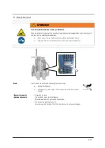
Switching from Up-cut to down-cut 


NOTICE


Invert the running direction at standstill only 

Inverting the running direction, allows up-cutting or down-cutting operations as required. 


Severe damage to the gearbox if operated incorrectly.  


Only change gears with the engine stopped.  


Wait for all parts to stand still. 


Sequence 


Switch off ignition 


Wait for all parts to stand still 


Move lever to desired positon 


Left =  up-cut 
center =  neutral 
Right =  down-cut


Summary of Contents for MULTICUT 605 SG

Page 1: ...1 107 OPERATING MANUAL FLOOR SAW MULTICUT 605 SG LISSMAC Maschinenbau GmbH Lanzstrasse 4 D 88410 Bad Wurzach Telefon 49 0 7564 307 0 Telefax 49 0 7564 307 500 lissmac lissmac com www lissmac com EN ...

Page 2: ...2 107 ...

Page 3: ...smac lissmac com www lissmac com Original operating manual Issue date 05 2020 Save this manual for future reference Distribution and duplication This operating manual must not be disclosed or reproduced in any form or its contents used without written permission to do so Breaches will result in claims for compensation All rights reserved in the event of patent registered design or design patent re...

Page 4: ...UTION This signal word indicates a dangerous situation If the situation is not avoided the consequence will be medium and minor injuries The hazard symbol may give details of the danger NOTICE This signal word indicates a situation which may present a danger for property If the situation is not avoided the consequence will be property damage This signal word is shown without a hazard symbol Import...

Page 5: ...table work clothes and wash regularly Attachment point for crane transports Remove the ignition key before working on the unit Engage or release parking break only at standstill Cutting hazard at the rotating tool Wait for all parts to stop Do not relocate the machine with rotating tool Extremely flammable fuel vapors Warning of crushing hazard Ejected parts hazard Warning of suspended loads ...

Page 6: ...ard Electrocution hazard from buried power lines Do not use high pressure cleaners Use by unauthorized persons not permitted No smoking Hazardous material fine silica dust Do not work on machine while the tool is spinning Instruction for damage prevention Lashing point for vehicle transport Only transport in an upright position Sound power level of the machine Visual check ...

Page 7: ...ing regulations for accident prevention which apply in the user s country and at the place of use the acknowledged rules for safe and correct working practice must also be observed Tools required A tool in the form of a saw blade is required for operating the floor saw These tools can be purchased from the manufacturer Further documents In addition to this operating manual further documentations f...

Page 8: ...8 107 Notes ...

Page 9: ...by crane 32 5 3 Tie down for transport 33 6 Control Desk 34 6 1 Multifunction display 35 7 Operation 37 7 1 Safety 37 7 2 Parking lock 39 7 3 Start preparations 40 7 4 Weight plates optional 40 7 5 Adjusting lowering speed of saw arm 41 7 6 Adjusting the handlebars 41 7 7 Gear selection 42 7 8 Switching from Up cut to down cut 43 7 9 Motor starting and stopping 44 7 10 Thrust angle adjustment 45 7...

Page 10: ...10 107 8 10 Maintenance plan 68 9 Tools 69 10 Warranty 70 11 Circuit diagram 72 12 Appendix A Error Code Liste HATZ 76 ...

Page 11: ... resistant sheet metal design Compact and well balanced chassis for easy maneuvering Extremely low center of gravity for precise cuts Very good straight cutting properties due to tunable rear axle Electro hydraulically controlled saw blade lift Height adjustable handlebars Hinged split blade guard for near wall cuts comes as standard Fast left to right cut conversion Easy access to maintenance com...

Page 12: ...s set out in the operating manual In particular faults which may adversely affect its safety must be rectified immediately Intended use The LISSMAC floor saw belongs to the floor cutting off machines and is designed exclusively for wet cutting joints in concrete or asphalt The cutting requires a tool in form of a diamond saw blade The floor saw may only be operated by one person The operator must ...

Page 13: ...uctions in the operating manual Always use the required and prescribed personal protective equipment Observe all safety and danger notes at the floor saw and keep them in readable condition Replace any damaged or illegible safety information and warnings With safety related changes of the machine or its operational behavior shut the machine down immediately and mark it accordingly Report the fault...

Page 14: ...rk on the electrical equipment on the machine may only be carried out by a qualified electrician or by trained personnel under the management and supervision of a qualified electrician and in compliance with the electronic regulations The operator must be named as the person responsible for traffic related regulations and make it possible for him to reject unsafe instructions by third parties Only...

Page 15: ...not use any unsafe method of working Take measures to ensure that the floor saw is only used if it is safe and in functional condition Check the floor saw at least once per shift for external signs of damage and defects Notify the responsible place person immediately when changes have occurred including the operational behavior If necessary shut down the machine immediately and secure it to preven...

Page 16: ...asons Electric motors switches and plug connectors are at particular risk Remove the covers masking tape completely after finishing the cleaning work Always retighten all screw connections loosened during maintenance and repair work If the disassembly of safety devices is necessary for setup maintenance and repair they are to be reassembled and checked immediately after conclusion of maintenance o...

Page 17: ...ng during cutting the saw blade must be continuously sprayed with water Dry cutting is prohibited Do not eat drink or smoke in the work area 2 5 4 Noise See section 3 3 2 5 5 Exhaust fumes Machines with internal combustion engine must not be operated indoors or in confined spaces 2 6 Transport Lifting gear of sufficient load bearing capacity must be used when transferring by crane Check lifting ge...

Page 18: ...immediately for repair If the machine is not operated immediately after unpacking it must be protected against humidity and dirt 2 8 Environmental protection Packaging material cleaning products used or residual media and unpacked wearing parts such as drive belts or engine oil must be recycled in accordance with the national environmental protection regulations in force at the place of use 2 9 Wa...

Page 19: ...rts Pos 1 Handle bars Pos 7 Pointer Pos 2 Emergency Stop button Pos 8 Blade guard Pos 3 Air filter Pos 9 Chassis Pos 4 Lifting eye Pos 10 Drive axis Hydrostat Pos 5 Diesel engine Pos 11 Water pump with ball valve Pos 6 3 speed gearbox 2 3 4 5 7 9 10 11 1 6 8 ...

Page 20: ...l speed 2 gear 1620 1 min Nominal speed 3 gear 2450 1 min Engine HATZ 4 Zylinder Turbodiesel EU Stage V EPA Tier 4 final Power kW PS 55 kW 74 8 PS 73 7 HP Fuel type Diesel Fuel tank size 32 Liter 8 4 gal Forward drive speed Hydrostat stepless 0 50 m min Reverse drive speed Hydrostat stepless 0 25 m min Saw blade lifting mechanism Electro hydraulic Saw blade drive V belt Weight 1070 kg 2360 lbs Len...

Page 21: ... saw under load Measurement tolerances 2 5 dB for the A weighted sound power level 4 dB for the A weighted emission sound power level The emission sound power level was measured in consideration of the EN ISO 3744 and EN 13862 standards and the 2000 14 EC Directive 3 4 Exhaust fumes DANGER Poisonous exhaust fumes The exhaust gases of the internal combustion engine contain carbon monoxide It is inv...

Page 22: ...aks when working with the machine The specified value was determined with the maximum saw blade diameter of 1000 mm The impact may be inversely proportional to the weight of the operator Total vibration value Multicut 605 SG aHV below 2 5 m s2 The following standards were applied for the measurements EN ISO 5349 VD 2057 Part 2 2002 42 EC Directive ...

Page 23: ...50 The use of lower qualities will halve the maintenance intervals and the warranty may be voided Lubricant Only use quality grease on the grease nipple The manufacturer uses Energrease LS2 BP Lithium based multi purpose grease of NLGI grade 2 according to DIN 51818 NLGI GC LB grade 2 Hydraulic oil The hydraulic fluid used must be of HVLP High Volume Low Pressure quality according to DIN 51524 3 I...

Page 24: ...ely Selecting a saw blade See section 9 Tools Storing tools The tools used must be protected from moisture The diamond segments must be protected from damage Blade speeds For best cutting results the saw blade speed must be adjusted to the aggregate to be cut Saw blade speed is governed by the Engine RPM and can be monitored on the multi function display Blade RPM Concrete Asphalt Blade diameter ...

Page 25: ...trol panel The pump has a sieve insert and a transparent plastic cover for daily inspection and cleaning WARNING Explosion hazard The pump may only be used for pumping water There is a risk of explosion if combustible liquids are pumped with it Use pump only for water Connection The water pump is plugged in the switchable socket next to the marked rocker switch on the control board water pump rock...

Page 26: ...ng the process Remove all sources of ignition Do not overfill tank or spill fuel NOTICE Store fuel safely Fuel must only be stored in approved containers The containers must be marked accordingly Sequence Stop engine Clean tank lid then open Fill in fuel with a clean funnel Do not spill do not overfill Securely close lid DIESEL ULSD ...

Page 27: ...Secure the machine against restart Always check saw blades before installation Blade for wet cutting 1 Blade suitable and approved for cutting work 5 Blade and holder are of the right size 2 7 Permissible cutting speed maintained 3 4 Direction of rotation 6 All segments available Blade was overheated bare steel blue tarnish do not use No cracks in the blade Check Knock with piece of wood Blade rev...

Page 28: ...f rotation and align marking on the blade with cutting shaft rotation up cut down cut The machine is delivered with the 35mm flange The 24 5 mm version is in the scope of delivery However it does not provide internal flange water supply The water has to be supplied externally via a spray fork Sequence Place saw blade on arbor Mount pressure disc Pos 4 and flange bolts Pos 3 and tighten evenly in a...

Page 29: ...ly perform this work with the engine turned off and pulleys standing still Check V belt tension can be checked by pushing them with a finger Remover the belt cover Check by pushing with a finger the drive belts must yield about one belt strength Effects of incorrectly tightened drive belts Drive belts too loose The drive belts slip on the V belt sheave Excessive wear and no or poor power transmiss...

Page 30: ...tallation or replacement of belts Remove bolts Pos 1 an belt drive guard Loosen locking bolt Pos 2 and slacken the belts with tension bolt Pos 3 evenly on both sides Remove worn belts check sheaves for damage and wear and install new belts Tension belts evenly on both sides to the colored marking Pos 4 Always apply even tension to both sides when tensioning the belts same number of notches Tighten...

Page 31: ...ge inclined positions must be avoided during the transport of the floor saw Fuel can spill or engine oil can enter the combustion chamber of the motor and damage the motor Maximum inclination in all directions 30 Only transport in an upright position All movable parts which could fall swing during transport must be removed Transport position Stop engine Activate parking lock Remove blade guard Rem...

Page 32: ...the transport position Sequence Establish the transport position see 5 1 Hang the floor saw into the crane lug with a slinging means with sufficient load capacity Appoint a competent signalperson for the lifting process Use only a suitable transport vehicle with sufficient load capacity Lift carefully and observe the center of gravity Always keep an eye on the floor saw For recommissioning proceed...

Page 33: ...w in transport position Secure the floor saw over the attachment points Use suitable lifting and lashing straps Observe maximum payload of the transport vehicle Tie down points Sequence Establish transport position see 5 1 Use suitable and sufficient lashing equipment and tie down points NOTICE Tie down bar The tie down bar is inserted in the frame on the same side the sawblade is mounted ...

Page 34: ...the saw arm Pos 3 Water pump on off Pos 12 Parking lock Pos 4 Socket for water pump 12V max 15A Pos 13 Clutch for traction drive Pos 5 Socket DC 12V max 10A Pos 14 Multifunction display Pos 6 Engine throttle Pos 15 Emergency stop button Pos 7 Throttle valve for saw am lowering speed Pos 16 Diesel Tank Pos 8 Cutting depth gauge Pos 17 Rope clamp for steering rod Pos 9 Ignition switch Pos 18 Enable ...

Page 35: ...ght remain lit until the engine is running Warning lights Pos 1 Service interval Pos 2 General engine malfunction Pos 3 Preheating Pos 4 Fuel level warning Pos 5 Battery Alternator malfunction Pos 6 Engine oil level pressure LCD Display Pos 7 Current saw blade RPM Pos 8 Current Engine RPM Pos 9 Engine oil temperrature Coolant temperature alternating display Pos 10 Operating hours of machine 1 3 4 ...

Page 36: ...anual for details Engine malfunction If this warning signal indicates a general engine fault if it lights up while the engine is running Stop engine Check oil level check air filter check coolant level also see engine operating manual for details Battery Alternator malfunction Lights up with active ignition and goes out when the motor is running If signal lights up during operation the alternator ...

Page 37: ...ghting at night Only cut in a straight line DANGER Poisonous exhaust fumes The exhaust gases of the internal combustion engine contain carbon monoxide It is invisible odorless and tasteless and can cause unconsciousness and suffocation It can quickly accumulate in confined spaces and stay there for hours even after the engine has been turned off Never operate machines with internal combustion engi...

Page 38: ...o be cut off CAUTION Burn hazard The engine parts like muffler and tailpipe become hot during operation and may cause burns Avoid skin contact Wear personal protective equipment Allow parts to cool before performing work For option GH WARNING High pressure fluid injection hazard A pinhole in a damaged high pressure hydraulic hose can inject oil under the skin This can cause gangrene and may lead t...

Page 39: ...the machine is not in use NOTICE The parking lock serves exclusively to immobilize the machine Due to its cog style design it may ONLY be activated at standstill Any activation in motion will destroy the parking lock Sequence The parking lock is engaged via lever Pos 12 Machine must stand still Flip lever up to engage and pull it down to release parking lock parking lock engaged parking lock relea...

Page 40: ... suitable saw blade is correctly mounted The water cooling system is fully functional The handle bars are adjusted and secured The cutting area is cleared from any obstacles The parking lock is activated The saw blade must be in a lifted position no ground contact The drive lever must be in neutral center position 7 4 Weight plates optional Function Weight plates provide additional surface pressur...

Page 41: ...pen the throttle as you perform test runs to set the right lowering speed lower faster lower slower 7 6 Adjusting the handlebars The handlebars can be adjusted to fit the operator s preference Release eye bolt and clamp and insert handlebar Tighten clamp at desired position and secure by tightening the eye bolt ...

Page 42: ...ting to be adjusted to each saw blade diameter and aggregate to be cut Severe damage to the gearbox if operated incorrectly Only change gears with the engine stopped Wait for all parts to stand still The gears have to engage perceptibly in the correct position Selecting gears 950 1 min 2450 1 min 1620 1 min ...

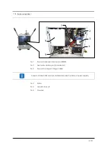
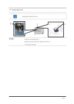
Page 43: ...ection allows up cutting or down cutting operations as required Severe damage to the gearbox if operated incorrectly Only change gears with the engine stopped Wait for all parts to stand still Sequence Switch off ignition Wait for all parts to stand still Move lever to desired positon Left up cut center neutral Right down cut ...

Page 44: ...ermanently alternating with the regular display and must be reset by a service employee if necessary Stopping 1 set the ignition key to 0 2 wait until the multifunction display is completely powered down and the display has gone out 3 only then can the power supply be disconnected DO NOT stop the machine via emergency stop NOTICE Use the Emergency Stop button only in case of an emergency If the em...

Page 45: ... Turn set screw Pos 1 clockwise thrust angle to the left counter clockwise thrust angle to the right 7 11 Adjusting the cutting depth stop The stepless depth stop limits the cutting depth of the saw blade to a preset depth This feature is recommendable for making several cut at the exact same depth Sequence Turn hexbolt clockwise decrease cutting depth Turn hexbolt counter clockwise increase cutti...

Page 46: ... abrupt lowering If the saw blade is lowered abruptly the blade can get bent and cutting segments may break off Lower saw blade gradually Set up a safety zone around the cutting area Wear personal protection equipment Always perform straight cuts and be careful not to cant or jam the saw blade in the kerf Perform all steering and control commands in a smooth and controlled fashion Deep cuts shall ...

Page 47: ...he surface and zero the depth gauge Pos 8 5 Gradually lower the saw blade via switch Pos 11 to the desired cutting depth 6 Adjust lowering speed with throttle valve Pos 7 if required 7 Release parking lock with lever Pos 12 8 Engage clutch for traction drive Pos 13 9 Initiate feed movement by gradually pushing drive lever forward Pos 10 10 Adjust feed speed to cutting conditions 11 Monitor cutting...

Page 48: ...sed and operated as prescribed The operator has to remain behind the handlebars during all cutting operation The floor saw may only be operated by a single person Instruct other persons to clear the work area Cordon off work area if required Maneuvering the floor saw Disengage traction drive Pos 13 Raise saw blade with switch Pos 11 to have ample ground clearance Deactivate the water pump with swi...

Page 49: ...mp with switch Pos 3 and close ball valve of water supply Set engine throttle forward to idle Pos 6 Activate parking lock Pos 12 at standstill Wait for saw blade to spin out to a standstill Switch off ignition Pos 9 and remove key NOTICE Storing the 3 speed gearbox During prolonged storage or periods of nonuse internal components will lose their lubrication film Start the machine or manually turn ...

Page 50: ...on Sequence Raise cutting shaft to top position and remove ignition key Uncouple water hose at top Pos 1 Remove blade guard diamond blade and flange see 4 5 Loosen hex bolt Pos 3 and remove flange guard Pos 4 Remove water cooling flange cover Pos 5 and mount it on the opposite side Pay special attention to the correct seating of the o ring Switch GEKA water hose connection at top of gearbox Pos 1 ...

Page 51: ...0W50 Pos 2 Neutral state monitoring unit for machine start Pos 3 Reservoir for cutting shaft lifting unit HV68 Hydraulic oil fill level HV 68 can only be checked correctly when the machine is lowered completely Pos 4 Battery Pos 5 Hydrostatic drive unit Pos 6 Diesel tank 6 1 3 4 2 5 ...

Page 52: ...d current rating Fuse Rating Function Holder 1 F1 35 A Main fuse F1 15 A Socket for Water pump F2 10 A Socket F3 10 A Socket F4 10 A Socket F5 15 A Oil cooler Option GH F6 Reserve F 30 A ECU E 10 A Fuel pump D 15 A Power supply C 40 A Glow plug B 1 A T15 50 control unit A 15 A Power supply ECU 1 F1 F A F1 F2 F3 F4 F5 F6 ...

Page 53: ...he machine always disconnect the negative battery pole and the electronic control system as far as possible 7 19 Air filter cartridge replacement The air filter retains the dust particles suspended in the ambient air and keeps from entering the engines combustion chamber The deposited particles gradually build up limiting the air flow to the engine Power is reduced and the engine may be damaged as...

Page 54: ...ence Stop engine Wait for all parts to stand still Open ball valve and drain water 7 21 Cleaning the water pump Check sieve daily before starting work Do not operate the pump without a sieve insert 1 Unscrew cover and remove sieve 2 Clean sieve insert using water and soft brush Caution Do not apply pressure to the mesh 3 Insert sieve and screw the cap Pay attention to proper fitting 1 2 ...

Page 55: ... 22 Checking engine oil level Check engine oil level daily before use Sequence Check oil level with dipstick Pos 1 Replenish as required via previously cleaned filler neck Pos 2 Do not spill Do not overfill 1 2 ...

Page 56: ...top engine and wait for all parts to stand still before working on the blade guard Sequence The front part of the blade guard can be folded up This function is used to make corner cut at walls Stop engine and wait for all parts to stand still Loosen bolts on side of blade guard Pos 1 Fold up front part Secure position by tightening bolt Pos 2 After the cut Stop engine Wait for all parts to stand s...

Page 57: ...clean the floor saw depending on the application Check engine oil and transmission oil level Change engine oil and transmission oil with respective filters every 6 Months or 250 operating hours Check air filter cartridge Replace air filter cartridge every 6 Months or if required Replace hydraulic oil and filter Initially after 100 then every 500 operating hours Grease at grease points Check safety...

Page 58: ...s essential for the proper operation and longevity of the drive Over tensioning can cause damage to the drive unit Maximum slack on the return strand may not exceed 10mm 0 4 in Sequence Remove back cover Adjust chain tension via Allen head screw Perform a short test run and check tension again ...

Page 59: ...ine all the way up and place a collection tray underneath Stop engine we recommend using a crane for securing the machine Unscrew protective cap Pos 1 from oil drain valve Integrated check valve oil will only flow with the drain hose being screwed on Screw on supplied drain hose and drain oil to collection tray Engine oil change interval Observe the engine manufacturer s operating instructions enc...

Page 60: ...ming service or maintenance work the engine has to be switched off Secure machine against inadvertent activation Service and maintenance work may only be carried out by qualified personnel Secure machine with a crane when working underneath ...

Page 61: ...ng hours Required Material Oil 20W50 ca 2 3L 4 Quarts Oil filter 1054655 Preparation Place flow saw on even ground and activate parking lock Lift blade shaft until frame is slightly tilted towards the back Remove back cover Clean area around the filter and expansion tank 1 2 3 C B A ...

Page 62: ...back plate C 5 Place the collection container underneath 6 Open the oil drain plug and drain the oil 7 Unscrew the oil filter Pos 3 8 Oil and screw in the seal of the new oil filter 9 Tighten the filter by hand 10 Screw in the oil drain plug again and fill in oil until the expansion tank is half full The gearbox must be purged after each oil change ...

Page 63: ...k through a 100 forward and 100 backward cycle 6 8 times wheels will spin Stop the engine Check the oil level in the expansion tank and fill it to about half Perform a test drive and recheck fill level NOTICE Repeat purging process It may be necessary to repeat the purging process if you experience thrust issues or the transaxle operates at elevated noise levels 8 6 Particular maintenance NOTICE S...

Page 64: ...hout regeneration short term use or if the catalyst is loaded at above 90 The operator must initiate the regeneration process manually We recommend a prompt execution in order to avoid damage to the catalyst or the activation of automatic engine protection measures The regeneration of the catalyst may take up to 35 min Refer to the engine manufacturer manual for further details Level Soot level of...

Page 65: ...the degree of soiling the process may take up to 35 minutes The exhaust gas temperature should be above 500 C during the entire process After a successful completion or after a 35 minute cycle the DPF symbol Pos 14 goes out Abort The process can be aborted at any time by initiating the drive function NOTICE Do not abort regeneration process We strongly recommend aborting the process only in an eme...

Page 66: ...se Solution Poor cutting performance Diamond blade is dull or not suitable Replace or exchange saw blade Not enough water Clean water strainer or Flush water supply system with a maximum of 5 bar Slipping v belts Retention v belts Engine does not generate full power Consult engine manufacturer manual Engine does not start Fuel tank empty Refuel Fuel filter clogged Clean or replace fuel filter Driv...

Page 67: ...que in Nm max tightening torque in Nm max tightening torque in Nm M4 3 3 4 8 5 6 M5 6 5 9 5 11 2 M6 11 3 16 5 19 3 M8 27 3 40 1 46 9 M10 54 79 93 M12 93 137 160 M14 148 218 255 M16 230 338 395 M18 329 469 549 M20 464 661 773 M22 634 904 1057 M24 798 1136 1329 M27 1176 1674 1959 M30 1597 2274 2662 ...

Page 68: ...on shall serve as proof maintenance already performed and as service booklet All maintenance and service work must be entered as proof Machine Type Serial number year of manufacture Date Implemented maintenance or service work Date signature ...

Page 69: ... purpose and area of application The parameters must be correct in order to achieve the best results The optimum cutting performance can be determined with this diagram The prices of the tools can be determined in the LISSMAC sales booklet This sales booklet can be obtained from the manufacturer at any time Tool storage Tools must be stored indoors in dry conditions The segments must be protected ...

Page 70: ...s clutches Water pneumatic or hydraulic valves and electric switches Guide elements such as guide bars guide bushes guide rails rollers bearings slide protection supports Clamping elements of fast separating systems Rinsing head seals Slide and rolling bearings which do not run in the oil bath Shaft seals and sealing elements Friction and overload clutches brakes Carbon brushes collectors Quick re...

Page 71: ...igter Leiter Konstruktion Technische Dokumentation Machine description The LISSMAC Floor saw pertains to floor cutting off machines and is exclusively intended for cutting joints in concrete or asphalt MULTICUT 600 SG Max cutting depth 515 mm Mas saw blade diameter 1200 mm Saw blade arbor 25 4 or 35 mm 6x M12 TK 120 mm Engine HATZ 4 Zylinder Turbodiesel EU Stage V EPA Tier 4 final Power rating kW ...

Page 72: ...72 107 11 CIRCUIT DIAGRAM ...

Page 73: ...73 107 ...

Page 74: ...74 107 ...

Page 75: ...75 107 ...

Page 76: ...76 107 12 APPENDIX A ERROR CODE LISTE HATZ ...

Page 77: ...77 107 ...

Page 78: ...78 107 ...

Page 79: ...79 107 ...

Page 80: ...80 107 ...

Page 81: ...81 107 ...

Page 82: ...82 107 ...

Page 83: ...83 107 ...

Page 84: ...84 107 ...

Page 85: ...85 107 ...

Page 86: ...86 107 ...

Page 87: ...87 107 ...

Page 88: ...88 107 ...

Page 89: ...89 107 ...

Page 90: ...90 107 ...

Page 91: ...91 107 ...

Page 92: ...92 107 ...

Page 93: ...93 107 ...

Page 94: ...94 107 ...

Page 95: ...95 107 ...

Page 96: ...96 107 ...

Page 97: ...97 107 ...

Page 98: ...98 107 ...

Page 99: ...99 107 ...

Page 100: ...100 107 ...

Page 101: ...101 107 ...

Page 102: ...102 107 ...

Page 103: ...103 107 ...

Page 104: ...104 107 ...

Page 105: ...105 107 ...

Page 106: ...106 107 ...

Page 107: ...107 107 ...

Reviews: