background image

Page

Page

3

+

Date

Replaced by

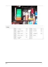
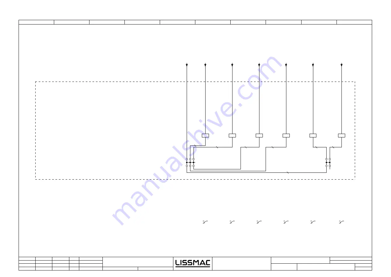
Relaissockel I
relay socket I

1

0

7

6

Checked

Replacement from

8

9

3

11

5

4

19.05.2017

4

2

=

Name

5

Unicut 520

Original

Date

Modification

Changed

Pfender

2,5

NOT-AUS
Emergency stop

-3A0

/3.0

GND

Port 1

Steckdose
Wasserpumpe
socket water
pump

Steckdose
1
socket 1

Steckdose
2
socket 2

Steckdose
3
socket 3

Steckdose
4
socket 4

85

86

-K3

87a

30

87

/3.2

85

86

-K4

87a

30

87

/3.3

85

86

-K5

87a

30

87

/3.4

85

86

-K1

87a

30

87

/3.1

85

86

-K2

87a

30

87

/3.2

0,75 mm²

0,75 mm²

0,75 mm²

0,75 mm²

85

86

-K6

87a

30

87

/3.4

0,75 mm²

0,75 mm²

1,5 mm²

ECU_LM_193

/

20.1

-ECU_LM_107

/

20.2

-ECU_LM_106

/

20.2

-ECU_LM_194

/

20.2

-ECU_LM_241

/

20.3

-Kl31

/

1.1

-Kl15_NA

/

7.3

Summary of Contents for UNICUT 520

Page 1: ...1 92 OPERATING MANUAL FLOOR SAW UNICUT 520 LISSMAC Maschinenbau GmbH Lanzstrasse 4 D 88410 Bad Wurzach Telefon 49 0 7564 307 0 Telefax 49 0 7564 307 500 lissmac lissmac com www lissmac com EN...

Page 2: ...2 92...

Page 3: ...07 0 Fax 49 0 7564 307 500 lissmac lissmac com www lissmac com Original operating manual Issue date 9 2018 This operating manual must not be disclosed or reproduced in any form or its contents used wi...

Page 4: ...TION This signal word indicates a dangerous situation If the situation is not avoided the consequence will be medium and minor injuries The hazard symbol may give details of the danger NOTICE This sig...

Page 5: ...ective helmet Wear work clothes and wash regularly Attachment point for crane transports Remove the ignition key before working on the unit Cutting hazard at the rotating tool Wait for all parts to st...

Page 6: ...ning of electric shock due to damaged power lines Battery hazards Explosion hazard Do not use high pressure cleaners Use by unauthorized persons not permitted No step area No Smoking Lashing point for...

Page 7: ...cing inspection and repair and or Transport In addition to the operating manual and the binding regulations for accident prevention which apply in the user s country and at the place of use the acknow...

Page 8: ...8 92 Notes...

Page 9: ...s 20 3 3 Technical specifications 21 3 4 Sound power level 22 3 5 Exhaust fumes 22 3 6 Hand Arm vibration 23 4 Commissioning 24 4 1 Connections and media 24 4 2 Tools saw blade 24 4 3 Water pump 25 4...

Page 10: ...8 10 Diesel Particulate filter DPF Optional 59 11 Maintenance 60 11 1 Servicing 60 11 2 Maintenance intervals 61 11 3 Air filter clogged 62 11 4 Cleaning the water pump 63 11 5 Access to maintenance h...

Page 11: ...um weight distribution low center of gravity Large sized fuel tank reduces downtime Quick change from left to right cut 180 degree swiveling Large non marking drive wheels Diagonal cuts to the inside...

Page 12: ...ng manual In particular faults which may adversely affect its safety must be rectified immediately Intended use The LISSMAC floor saw belongs to the floor cutting grinder and is designed exclusively f...

Page 13: ...tions in the operating manual Always use the required and prescribed personal protective equipment Observe all safety and danger notes at the floor saw and keep them in readable condition Replace any...

Page 14: ...work Work on the electrical equipment on the machine may only be carried out by a qualified electrician or by trained personnel under the management and supervision of a qualified electrician and in c...

Page 15: ...ve or broken tools must be replaced immediately 2 4 3 Operation Do not use any unsafe method of working Take measures to ensure that the floor saw is only used if it is safe and in functional conditio...

Page 16: ...s masking tape completely after finishing the cleaning work Always tighten screw connections rendered loose during maintenance and repair work If the disassembly of safety devices is necessary with th...

Page 17: ...saw blade must be continuously sprayed with water Dry cutting is prohibited Do not eat drink or smoke in the work area 2 5 4 Noise see section 3 4 2 5 5 Exhaust gases Machines with internal combustion...

Page 18: ...manufacturer immediately If the machine is not operated immediately after unpacking it must be protected against humidity and dirt 2 8 Environmental protection Packaging material cleaning products us...

Page 19: ...rod Pos 7 Control panel Pos 2 Blade guard Pos 8 Driver seat Pos 3 Suction shoe Pos 9 Control unit compartment Pos 4 Footboard Pos 10 Exhaust pipe Pos 5 Cutline indicator Pos 11 Steering rod Pos 6 Mou...

Page 20: ...tem 5 Socket 4 12V 10A switchable Item 6 Socket 5 12V 10A constant current Water Item 7 Water connection max 5 bar Diagnosis Item 8 Connecting plug diagnosis only for service Controller Item 9 Control...

Page 21: ...y stepless 0 60 m min Backward cutting motion Hydraulically stepless 0 60 m min Saw blade speed 850 2900 1 min 600 2900 1 min Weight 1990 kg 4387lbs Internal combustion engine DEUTZ Turbodiesel 4 Cyli...

Page 22: ...The emission sound power level was measured in consideration of the EN ISO 3744 and EN 13862 standards and the 2000 14 EC Directive 3 5 Exhaust fumes DANGER Poisonous exhaust gases The exhaust gases o...

Page 23: ...breaks when working with the machine The specified value was determined with the maximum saw blade diameter of 1000 mm The impact may be inversely proportional to the weight of the operator Total vibr...

Page 24: ...y may be voided Lubricant Only use quality grease on the grease nipple The grease used on the floor saw has the name Energrease LS2 BP Lithium based multi purpose grease of NLGI grade 2 according to D...

Page 25: ...There is a risk of explosion if combustible liquids are pumped with it Power supply connection Connect the water pump only to the designated socket This connection is fused with a higher rating 15A 4...

Page 26: ...e 2 7 Permissible cutting speed maintained 3 4 Direction of rotation 6 All segments available Blade was overheated bare steel blue tarnish do not use No cracks in the blade Check Knock with piece of w...

Page 27: ...this purpose Sequence The driver s seat can be infinitely adjusted in height as well as in the set up with other modules and adapted to the needs of the operator Release clamping screw item 1 and adju...

Page 28: ...ator requires a release by the seat switch to start driving functions The floor saw is operated via the joystick and the operator can call up various menus on the display where all relevant data can b...

Page 29: ...down Fine steering for precise steering corrections in cutting operation Steering modes 1 2 Steering mode 1 controlled If the joystick is tilted to the right or to the left the wheels will follow the...

Page 30: ...in cutting operation Steering modes 1 2 Steering mode 1 controlled If the joystick is tilted to the right or to the left the wheels will follow the deflection angle of the joystick and remain in this...

Page 31: ...ation legibly both during the day and at night Home The operator can access various menus to view and change values and the machine settings Item 1 Rotary push button control Turning this button selec...

Page 32: ...Pos 6 Freely assignable see 5 2 4 Pos 7 Freely assignable see 5 2 4 Pos 8 Diesel tank fill level indicator DSL Pos 9 Diesel engine warning orange warning red fault Pos 10 Display of the saw blade rot...

Page 33: ...for slurry extraction auto manual Pos 6 Button display for steering mode 1 2 Pos 7 Selection display for deep cutting Pos 8 Selection display for lateral cutting Pos 9 Input field for speed for rapid...

Page 34: ...9 Selection for multifunction button 3 switchable socket 3 or Item 10 Selection for multifunction button 3 switchable socket 4 Dashboard settings The pre selection is made via the rotary push button c...

Page 35: ...em 4 List of detected faults FMI FMI Failure Mode Identifier fault code 1 GND short circuit 2 UB short circuit 4 cable break 5 6 common fault Item 5 Line upwards COUNTER The number of seconds the faul...

Page 36: ...Item 2 Overview direct selection button Item 10 Charge air filter pressure Item 3 Engine speed Item 11 Accelerator pedal position Item 4 Cooling water temperature Item 12 Fuel consumption Item 5 Batte...

Page 37: ...n Item 3 Display brightness Item 4 Button brightness Setting the brightness On the start page use the direct selection button item 2 to select the Display settings menu Select the area to be adjusted...

Page 38: ...button Item 3 Level selection 1 4 Item 4 Input field 7 digit service code password Item 5 Exit window Item 6 Keypad for entry using the rotary push button control Item 7 Green level enabled according...

Page 39: ...straps NOTICE Machine transport When transporting the floor saw unintentional changes in position must be avoided Engine oil can run into the combustion chamber of the engine and damage the engine Ma...

Page 40: ...at the right speed Start combustion engine Set the engine speed rotary knob item 1 to the lowest possible position If necessary release emergency stop item 3 Move joystick item 2 to the middle positi...

Page 41: ...permost position For rapid traverse the operator must sit on the seat In addition the button no 6 on the joystick underside must be pressed Seat safety circuit The floor saw has a safety device which...

Page 42: ...Sequence Establish transport position see 6 1 Suspend the floor saw into the crane eyelets using a sling with sufficient load bearing capacity Avoid inclined positions Determine a competent instructor...

Page 43: ...only in the transport position Secure machine via lashing points Use suitable and undamaged load securing equipment Establish the transport position All moving parts that could fall off swing or distu...

Page 44: ...s Keep the machine clean and operate only in a technically flawless condition Ensure stable water supply Remove all obstacles from the cutting area Ensure good lighting at night Make only straight cut...

Page 45: ...a dust During the cutting process fine silica dust can develop which irreversibly damages the lungs silicosis Wear personal respiratory protection Change and wash dusty work clothes after the end of t...

Page 46: ...oling water The saw blade overheats if it is not sufficiently cooled with water Segments can break out and parts hurled around Always cool the saw blade with enough water Wear personal protective equi...

Page 47: ...r button 3 on joystick Switch on saw blade drive using button 4 on the joystick Set combustion engine to full throttle Adjust saw blade speed according to table below Using the thumbwheel A on the joy...

Page 48: ...the rotary push button and activate by pressing Activated symbols are white while inactive symbols are greyed out Options Activated Deactivated The activated comfort mode is displayed on the dashboar...

Page 49: ...e Press rotary switch item 1 to activate the middle menu Select first element item 16 and confirm by pressing the rotary switch item 1 By turning the rotary switch item 1 the toe in value can be set i...

Page 50: ...Place floor saw in parking position on firm ground Move the joystick to the neutral position Stop the machine and remove the ignition key Fold the steering rod up Install protective covers on control...

Page 51: ...ring rod Pos 4 and any hindering parts from the front assembly Install lifting cylinder Pos 5 on the other side of the machine readjust hydraulic lines if necessary Remove 2 tensioning screw Pos 5 at...

Page 52: ...slings or chains with sufficient load bearing capacity and length Sequence Stop combustion motor and remove ignition key Remove security bolts Pos 1 Select a pivot point an loosen the corresponding bo...

Page 53: ...ecured Do not step under a suspended load Only use undamaged slings or chains with sufficient load bearing capacity and length Sequence Remove sawblade and blade guard Suspend slider box from a crane...

Page 54: ...ic Adjust wheel to desired height Tighten bolts Tailpipe Loosen bolts Turn until the opening faces away from the operator Tighten bolts A Standard B with Diesel particulate filter Option Depth stop la...

Page 55: ...in roads Max Saw blade diameter 500 mm 19 5 in Max Cutting depth 175 mm 6 9 in Max Cut length with trolley 2 m 6 6 ft Weight 260 kg 573 lbs WARNING Cut and Crush hazard at chain drive and trolley Body...

Page 56: ...ver flor saw in position Fold down and adjust steering rod Saw blade must not turn Pull the lever to the horizontal position all the way Main cut Lateral cut Plausability fault HUD Establish water sup...

Page 57: ...ck that water is running Slowly lower the blade until it makes contact with the surface and lower blade guard Set depth gauge to zero Lower saw blade to desired depth using thumbwheel B Advance trolle...

Page 58: ...all parts to be stationary before performing any work on the machine Sequence Start engine and run trolley to end stop at operator seat Lift saw head all the way up Switch off engine and remove ignit...

Page 59: ...knowledge Pos 5 Alarm signal light SL Fault Display Cause 21 No LED Alarm signal light blinking Communication error CB PB 23 All LED blinking SL blinking low SW value between CB and PB 31 35 Pressure...

Page 60: ...d on electronic components Motor oil Only use DEUTZ approved motor oil Minimum quality is DQC III 10 LA If lower grade oils are used the service interval frequency will double and warranty may be void...

Page 61: ...e water supply filter Check hydraulic hoses and fittings for any leak and damage After 20 h Check cooler for contamination clean if necessary Screw connections Retighten all screw connections after 20...

Page 62: ...s work in more or less dusty environments As a result dust settles at different rates on the air filter To maintain full engine performance the air filter must be kept clean The engine therefore has a...

Page 63: ...ore starting work Do not operate the pump without a sieve insert 1 Unscrew cover and remove sieve 2 Clean sieve insert using water and soft brush Caution Do not apply pressure to the mesh 3 Insert sie...

Page 64: ...actory In order to reattach it in the correct position without realignment issues after servicing we recommend removing the bolts on the mainframe side Pos 1 Sequence Start engine and run trolley to e...

Page 65: ...eserve F8 Sensors LISSMAC 5 A F7 Reserve F7 Solenoids Valves 10 A F6 Socket 5 10 A F6 Reserve F5 Socket 4 10 A F5 Reserve F4 Socket 3 10 A F4 Deep Lateral cutting 10 A F3 Socket 2 10 A F3 Fuel pump 20...

Page 66: ...ating 100 A F6 Electronic 30 A F2 Socket water pump Socket 1 40 A F7 DEUTZ ECU 30 A F3 Socket 2 Socket 3 40 A F8 LISSMAC ECU 30 A F4 Socket 4 Socket 5 30 A F9 Reserve F5 Control panel fuel pump 30 A F...

Page 67: ...d Battery acid is corrosive Keep ignition sources away Pay attention to correct polarity Wear protective gloves and goggles Before welding work on the machine always disconnect the negative battery po...

Page 68: ...ed secure against restart Always wait until the saw blade has stopped before performing any maintenance work Maintenance and repair work may only be carried out by trained personnel Saw head and guide...

Page 69: ...al cutting unit SSE Hinge Grease SSE hinge monthly Pos 4 Saw head guides Grease saw head guides weekly Pos 5 Chain and sprocket Grease chain spray lubricant weekly Saw head shaft Grease shaft weekly P...

Page 70: ...operating instructions of the internal combustion engine Wrong saw blade speed Check saw blade speed Wrong saw blade direction of rotation Check saw blade direction of rotation Too little cooling wat...

Page 71: ...torque in Nm Max tightening torque in Nm Max tightening torque in Nm M4 3 3 4 8 5 6 M5 6 5 9 5 11 2 M6 11 3 16 5 19 3 M8 27 3 40 1 46 9 M10 54 79 93 M12 93 137 160 M14 148 218 255 M16 230 338 395 M18...

Page 72: ...to keep a record of maintenance work already completed and as a service record All maintenance and service work must be entered to create a full record Machine Type Serial number Year of manufacture...

Page 73: ...mond tools are color coded The tools differ depending on the area and scope of application For the best results the parameters must be correct With this diagram the optimum cutting performance can be...

Page 74: ...s and belts Seals cables hoses sleeves plugs couplings and switches for pneumatic hydraulic water electric and fuel systems Guide elements such as guide strips guide bushes guide rails rollers bearing...

Page 75: ...ed for wet cutting joints in concrete or asphalt Cutting comprises saw blades up to a maximum of 1500 mm UNICUT 520 107 UNICUT 520 160 Cutting depth 630 mm 25 Max saw blade 1500 mm 59 Saw blade holder...

Page 76: ...76 92 14 CIRCUIT DIAGRAM...

Page 77: ...ronik electronic 1 2 F1 100A Vorheizung preheating 1G0 1 2 F4 30A Steckdose F3 socket F3 1 2 F8 30A Lissmac Leistung Steuerger t Lissmac Power control unit Masse 1A2 1 2 F3 40A Steckdose F3 socket F3...

Page 78: ...erator Generator Anlasser starter Vorheizrelais preheating relay R1 1 Gl hkerze glow plug 2A2 1 R1 2 Gl hkerze glow plug R1 3 Gl hkerze glow plug R1 4 Gl hkerze glow plug M 2M7 Kl 30 G 2G5 B D W 30 87...

Page 79: ...2 3XS2 1 2 3XS3 1 2 3XS4 1 2 3XS5 1 2 3XS6 Steckdose Wasserpumpe socket water pump 1 2 F1 15A Wasser pumpe water pump 1 2 F6 10A Steckdose 5 socket 5 1 2 F7 Reserve Spare 1 2 F5 10A Steckdose 4 socke...

Page 80: ...rt 1 Steckdose Wasserpumpe socket water pump Steckdose 1 socket 1 Steckdose 2 socket 2 Steckdose 3 socket 3 Steckdose 4 socket 4 85 86 K3 87a 30 87 3 2 85 86 K4 87a 30 87 3 3 85 86 K5 87a 30 87 3 4 85...

Page 81: ...1 2 F4 10A Umschaltung Tiefen Seitenschnitt switch depth side cut 1 2 F8 5A Sensoren Lissmac Sensors Lissmac 1 2 F9 Reserve Spare 1 2 F10 Reserve Spare 1 2 F1 2A Bedien pult operator station 1 2 F3 20...

Page 82: ...5 Unicut 520 Original Date Modification Changed Pfender NOT AUS Emergency stop 2 5 0 75 0 75 Kraftstoff pumpe fuel pump Umschaltung Tiefen Seitenschnitt switch depth side cut 5A0 5 0 Port 2 85 86 K1...

Page 83: ...5 7X5 CAN L CAN L 7X4 CAN H CAN H 7R5 Abschlusswiderstand terminating resistor 120 30 58 Aus 15 54 50a 7S1 Z nd schloss ignition switch 2 4 3 1 2 2 12 13 12 13 2 7S6 1 3 11 11 10 10 5 5 1 7XS8 2 1 7XP...

Page 84: ...3 socket 3 Steckdose 4 socket 4 Endlage Seitenschnitt final position side cut Endlage Tiefenschnitt final position depth cut Lenken links steer left Lenken rechts steer right Fahren vor drive ahead F...

Page 85: ...nating resistor Vorheizen preheating CAN 0 IN Z ndung Einschalten ignition switch on Customer CAN Diagnose CAN Kraftstoff pumpe fuel pump Vorheizen preheating Neutral neutral Vorheizen preheating Absc...

Page 86: ...ide cut saw blade up down Umschaltung Tiefenschnitt S gehaube auf ab Seitenschnitt Vorschub vor zur ck switch depth cut saw blade protection hood up down side cut feed forward backward berwachung S ge...

Page 87: ...87 92 15 HYDRAULIC DIAGRAM SCEMATIC...

Page 88: ...88 92...

Page 89: ...89 92...

Page 90: ...ng wheel x x 36947 Fault radio link x x Sensors 213 DRZ Sensor A2FM x x 236 DRZ Sensor Direction A2FM x x 209 Seat switch presence indicator x x 147 Oil temperature switch x x 223 Oil Level switch x x...

Page 91: ...Prop Blade guard lift x x 184 Prop Saw blade lift x x 185 Prop Saw blade lower x x 186 Prop Suction unit x x 179 Prop Blade guard lower x x 180 Prop Cutting hydraulic motor x x Power switching output...

Page 92: ...92 92...

Reviews: