background image

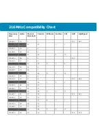
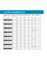
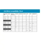
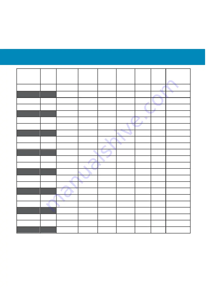
216 MHz Compatibility Chart


Frequency


MHz


Listen


Phonak


Microfield 


Comtek


Williams


Gentner


CSI


AVR


LightSpeed


216.4125


1J


17


17


C21


216.425


2J


49


49


G


9


18


216.4375


3J


18


18


216.5125


1K


61


21


216.525


2K


29


51


H


10


3


216.5375


3K


62


22


216.5625


1L


28


23


216.575


2L


52


52


I


11


12


216.5875


3L


64


24


C24


N64


216.6125


1M


65


25


C25


216.625


2M


53


53


J


12


8


216.6375


3M


81


26


216.6625


1N


82


27


216.675


2N


54


54


K


13


16


216.6875


3N


68


28


216.7125


1P


69


29


C29


216.725


2P


55


55


L


14


19


216.7375


3P


83


30


216.7625


1R


84


31


216.775


2R


56


56


15


4


216.7875


3R


72


32


C32


N72


216.8125


1S


73


33


C33


216.825


2S


57


57


13


Summary of Contents for ListenPoint LPT-T216

Page 1: ...Welcome Let s get started ...

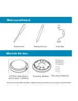
Page 2: ...king Pencil Hole Saw What s in the box LPT T216 ListenPoint ALS Module 216MHz Mounting Platform Mounting Hardware If you did not receive all listed parts please call Listen Technologies Corporation See back page for contact information ...

Page 3: ...Items to Remember The distance between the T216 ALS Transmitter and the Room Module should only be a maximum of 50 ft 15 m The T216 ALS Transmitter broadcasts an FM signal FM signal will travel through walls and other visual obstructions Appropriate attention needs to be paid to placement of the transmitter for optimal privacy and performance within the room Do not cut into ceiling without safely ...

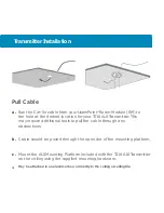
Page 4: ...tter This may require additional tools to pull the cable through any obstructions b Cable should be pulled through the open slot of the mounting platform c Mount the ALS Mounting Platform included with the T216 ALS Transmitter on the ceiling using the supplied mounting hardware May be attached to an electrical box or directly to the ceiling or ceiling tile ...

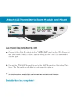
Page 5: ...RM a Connect the Cat 5e cable to the LISTEN BUS port on the RM Connect the other end of the Cat 5e cable directly to the T216 ALS Transmitter via the port b Mount the T216 ALS Transmitter onto the ALS Transmitter Mounting Plat form The Transmitter will slide in and snap into place To snap into place simply align notches and turn clockwise until it snaps Installation is complete ...

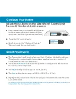
Page 6: ... Microphones Auto Select On Select Power Level a The Transmitter has 3 levels of power High Medium default and Low This allows for customizable transmission applications in a variety of environments and circumstances b The default Medium level has the optimal coverage for a standard 30 ft x 30 ft 9 m X 9 m room c The High setting has a range of 150 ft 46 m d The Low setting has a range of 10 ft x ...

Page 7: ...ings 19 wide band and 38 narrow band Adjust the FM receivers to the desired channel b Tune the receivers to the transmission channel We recommend the use of genuine Listen wireless receivers and accessories for solid performance and the highest standards of quality ...

Page 8: ...ll the wide band channels via the headphone jack on a Listen receiver Us ing the frequency compatibility tables on page 9 eliminate any chan nels that have noticeable interference Now choose the channels with the widest channel spacing It is recommended that adjacent chan nels be spaced at least 300 kHz If there is no interference the following channels are recommended Channels 2A 2K and 2V at 216...

Page 9: ...2 42 2 10 216 0875 3B 4 4 C05 216 1125 1C 5 5 216 125 2C 43 43 A 3 6 216 1375 3C 22 6 216 1625 1D 23 7 216 175 2D 44 44 B 4 14 216 1875 3D 8 8 216 2125 1E 9 9 C09 N09 216 225 2E 45 45 C 5 2 216 2375 3E 24 10 216 2625 1F 25 11 216 275 2F 46 46 D 6 11 216 2875 3F 12 12 C12 N12 216 3125 1G 13 13 216 325 2G 47 47 E 7 7 216 3375 3G 26 14 216 3625 1H 27 15 216 375 2H 48 48 F 8 15 216 3875 3H 16 16 C18 N...

Page 10: ... 2K 29 51 H 10 3 216 5375 3K 62 22 216 5625 1L 28 23 216 575 2L 52 52 I 11 12 216 5875 3L 64 24 C24 N64 216 6125 1M 65 25 C25 216 625 2M 53 53 J 12 8 216 6375 3M 81 26 216 6625 1N 82 27 216 675 2N 54 54 K 13 16 216 6875 3N 68 28 216 7125 1P 69 29 C29 216 725 2P 55 55 L 14 19 216 7375 3P 83 30 216 7625 1R 84 31 216 775 2R 56 56 15 4 216 7875 3R 72 32 C32 N72 216 8125 1S 73 33 C33 216 825 2S 57 57 1...

Page 11: ...ak Microfield Comtek Williams Gentner CSI AVR LightSpeed 216 8375 3S 76 34 216 8625 1T 85 35 216 875 2T 58 58 9 216 8875 3T 86 36 216 9125 1U 77 37 C37 N77 216 925 2U 59 59 17 216 9375 3U 88 38 216 9625 1V 79 39 C39 216 975 60 60 5 216 9875 80 40 C40 N80 ...

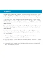
Page 12: ...r and Listen receivers If you are planning to use this product with older Listen systems that do not have Listen SQ or equipment not manufactured by Listen you should dis able Listen SQ Your Listen equipment has been shipped to you with the SQ feature en abled You may need to disable the SQ function for one or more of the following reasons a You are using your new Listen system with older version ...

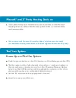
Page 13: ... the highest standards of quality Test Your System Power Up and Test the System a Push the power button on the CU turning on CU will also power the RM b Test the system with a fully charged microphone push any button on the microphone or simply remove from the Charging Storage Station to turn on Wait 10 Seconds and then adjust the volume on the micro phone until you have a comfortable listening le...

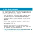
Page 14: ... to maximizing signal strength b Eliminate or minimize obstructions between the transmitter and the receivers c Minimize the distance between the transmitter and the receivers d Stay clear of metal objects e Keep the headphone cables connected to the receivers fully extended Do not shorten or coil headphone cables These cables are the antennas for your portable products If the RF signal to the 216...

Page 15: ...ates Navy SPASUR installations You do not need an FCC license to operate this transmitter This transmitter may only be used to provide auditory assistance to persons with disabilities persons who require lan guage translation or persons in educational settings health care services to the ill law enforcement tracking services under agreement with a law enforcement agency or automated maritime telec...

Page 16: ...es uses and can radiate radio frequency energy and if not installed and used in accordance with the instruction manual may cause harmful interference to radio communications Operation of this equipment in a residential area is likely to cause harmful interference in which case the user will be required to correct the interference at his own expense RF Safety Instructions For RF Safety and per FCC ...

Page 17: ...ntact the carrier then contact Listen for replacement or repair requirements payable by the carrier Listen s corporate headquarters are located in Bluffdale Utah U S A We are open Monday through Friday 8am to 5pm Mountain Time 14912 Heritagecrest Way Bluffdale Utah 84065 4818 1 801 233 8992 1 800 330 0891 North America 1 801 233 8995 fax support listentech com www listentech com ...

Page 18: ...and support listentech com listenpoint 2009 2013 by Listen Technologies Corporation All Rights reserved ListenPoint and the Listen logo are registered trademarks of Listen Technologies Corporation Other brand and product names are trademarks or registered trademarks are of their respective holders ...

Reviews: