background image

page 7

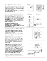
9. Blade Assembly.

Time Saver

: Washers for blade screws can be set 

on each blade screw prior to installing blades.

Locate 15 blade attachment screws and  washers 
in one of the hardware packs. Hold blade arm up 
to blade and align holes. Insert 3 blade 
attachment screws (along with washers) with 
fingers first and then tighten screws securely 
with a Phillips screwdriver. Repeat for the 
remaining blades.

Remove blade arm screws and lock washers 
from underside of motor. If plastic motor locks 
are installed with blade arm screws, discard 
plastic motor locks (

save blade arm screws and 

lock washers to secure blade arms

). Align blade 

arm holes with motor screw holes and attach 
blade arm with lock washers and blade arm 
screws. Before securing screws permanently, 
repeat with remaining blade arms. Securely 
tighten all screws.

NOTE:

 Tighten blade arm screws twice a year.

switch housing cap

light kit fitter

switch

housing

motor
housing

switch housing

cap

hex nut

lock washer

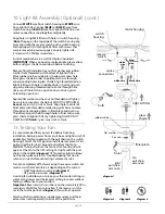
10. Light Kit Assembly.

Remove 3 screws from switch housing cap.


If you wish to use fan WITHOUT the light kit

align holes in switch housing cap with holes in 
switch housing. (

Note

: The gap on the top edge 

of the switch housing cap must align with the 
reverse switch on the switch housing for the 
proper fit.) Secure switch housing cap with 
3 screws that were just removed.


Please proceed to Section 11 on the next page to 
complete installation WITHOUT the light kit.


If you wish to use fan WITH the light kit

, locate 

BLUE

 (or 

BLACK

) and 

WHITE

 wires in switch 

housing labeled LIGHT.

 
Remove hex nut and lock washer from threaded 
rod on light kit fitter. Punch center cap out of 
switch housing cap with a screwdriver. Feed 
wires from light kit fitter through center hole in 
switch housing cap. Then, screw switch housing 
cap onto threaded rod followed by lock washer 
and hex nut. Tighten hex nut over lock washer 
for a secure fit.


["Light Kit Assembly" continued on next 
page.]

black (or blue)

wire

blade arm

blade

blade attachment

screws and washers

lock

washers

blade arm screws

motor housing

plastic
motor lock

center cap

white wire

switch housing cap

Summary of Contents for 1158921

Page 1: ...allation pg 3 Fan Assembly pgs 4 5 Wiring pg 6 Canopy Assembly pg 6 Blade Assembly pg 7 Light Kit Assembly Optional pgs 7 8 Testing Your Fan pg 8 Troubleshooting pg 9 Parts Replacement pg 9 Warranty p...

Page 2: ...n 12 gauge or there is more than one house wire to connect to the corresponding fan lead wires consult an electrician for the proper size wire connectors to use 5 Electrical diagrams are for reference...

Page 3: ...y 1 piece b hanging bracket 1 piece c downrod and hanging ball with pin and clip 1 piece d motor housing 1 piece e yoke cover 1 piece f blade arm 5 pieces g switch housing cap 1 piece h blade 5 pieces...

Page 4: ...iginal outlet box If installing on a vaulted ceiling face opening of hanging bracket towards high point of ceiling Arrange electrical wiring around the back of the hanging bracket and away from the ha...

Page 5: ...as having a set screw hole use this hole when setting the set screw Insert stop pin into top of extended downrod and raise hanging ball Be sure stop pin aligns with slots on the inside of the hanging...

Page 6: ...ide canopy cover to reveal 6 holes Refer to diagram 1 Notice that 3 of these holes are larger Locate 6 screws in top of motor housing yoke Observe that 3 of the screw heads are almost flush with the y...

Page 7: ...or provided Connect all GROUND GREEN wires together from fan to BARE GREEN wire from ceiling with wire connector provided If you intend to control the fan light with a separate light switch connect BL...

Page 8: ...x nut lock washer 10 Light Kit Assembly Remove 3 screws from switch housing cap If you wish to use fan WITHOUT the light kit align holes in switch housing cap with holes in switch housing Note The gap...

Page 9: ...lign holes in light kit fitter with holes in switch housing Note The gap on the top edge of the switch housing cap must align with the reverse switch on the switch housing for the proper fit Attach li...

Page 10: ...to a defect in material or workmanship Contact Litex Customer Service at 1 800 527 1292 to arrange for return of fan Return fan shipping prepaid to Litex Industries Ltd We will repair or ship you a re...

Reviews: