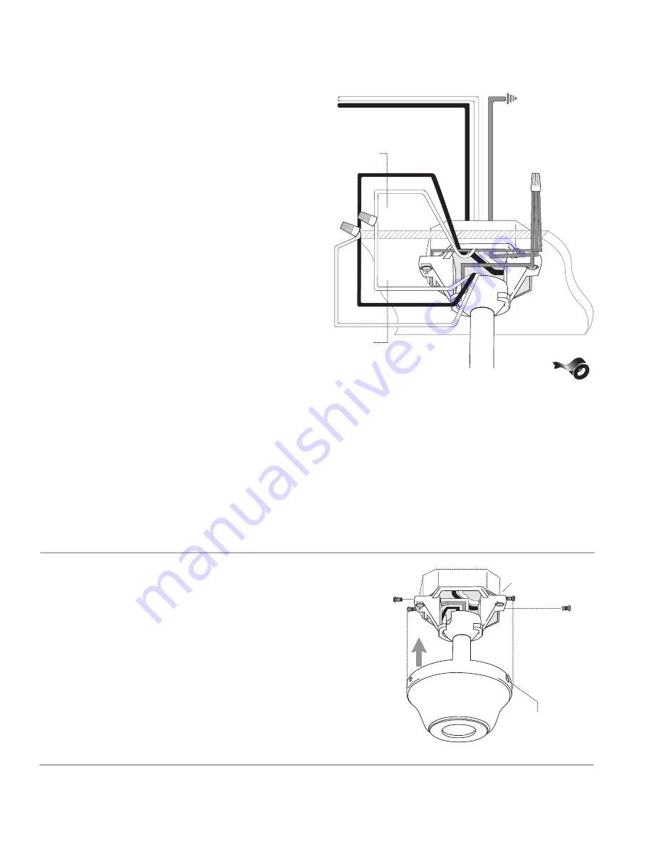
background image

7. Wiring.

page 6

8. Canopy Assembly.

Raise canopy to hanging bracket, aligning 
loosened screws in hanging bracket with slotted 
holes in canopy.  Twist canopy to lock. Re-insert 
screws (with washers) that were previously 
removed (on page 3, Section 4) and then secure 
all screws with Phillips screwdriver.

slotted

hole

CAUTION

Be sure outlet box is properly grounded 

and that a ground wire (

GREEN

 or Bare) is present.

Make sure all electrical connections comply with 
Local Codes or Ordinances and the National 
Electrical Code. If you are unfamiliar with electrical 
wiring or if the house/building wires are different 
colors than those referred to below, please use a 
qualified electrician.

When downrod is secured in place on the 
hanging bracket, electrical wiring can be 
made as follows:
Connect 

BLACK

 and 

BLUE

 wire from fan to 

BLACK

 wire from ceiling with wire connector 

provided.
Connect 

WHITE

 wire from fan to 

WHITE

 wire 

from ceiling with wire connector provided.
Connect all 

GROUND

 (

GREEN

) wires together 

from fan to 

BARE

/

GREEN

 wire from ceiling with 

wire connector provided.

If you intend to control the fan light with a 
separate light switch connect 

BLUE

 wire from 

fan  to the 

BLACK

 supply from the independent 

switch. 

* Wrap each wire connector separately with 
electrical tape as an extra safety measure.

This fan is remote control adaptable (remote 
control sold separately).

black

black

white

white

blue

black supply wire

ground (green
or bare)

white supply wire

*

from ceiling

from fan

ground 
(green or bare)

canopy

hanging bracket

Summary of Contents for E-DCF52BNK5C3

Page 1: ...sting Your Fan pg 8 Troubleshooting pg 9 Warranty pg 9 Parts Replacement pg 9 Installation Guide For Models E DCF52BNK5C3 E DCF52FBZ5C3 E DCF52MWW5C3 net weight of fan 15 65 lb 7 1 kg E89519 READ THESE INSTRUCTIONS AND SAVE THEM FOR FUTURE USE Federal regulations require ceiling fans with light kits manufactured or imported after January 1 2009 to limit total wattage consumed by the light kit to 1...

Page 2: ... or there is more than one house wire to connect to the two fan lead wires consult an electrician for the proper size wire connectors to use 5 Electrical diagrams are for reference only Light kits that are not packed with the fan must be UL listed and marked suitable for use with the model fan you are installing Switches must be UL general use switches Refer to the instructions packaged with the l...

Page 3: ...ventory that all parts have been included 2 Parts Inventory a canopy 1 piece b hanging bracket pre attached to canopy 1 piece c 4in downrod and hanging ball with pin and clip 1 piece d motor housing 1 piece e blade arm 5 pieces f blade 5 pieces g light kit fitter 1 piece h glass shade 3 pieces i hardware packs a b c d e IMPORTANT REMINDER You must use the parts provided with this fan for proper in...

Page 4: ...t box using original screws spring washers and flat washers provided with new or original outlet box If installing on a vaulted ceiling face opening of hanging bracket towards high point of ceiling Arrange electrical wiring around the back of the hanging bracket and away from the hanging bracket opening Note It is very important that you use the proper hardware when installing the hanging bracket ...

Page 5: ...longer downrod B the top of the downrod should be noted as having a set screw hole use this hole when setting the set screw Insert stop pin into top of extended downrod and raise hanging ball Be sure stop pin aligns with slots on the inside of the hanging ball Tighten set screw securely Tip To prepare for threading electrical wires through downrod apply small piece of electrical tape to the ends o...

Page 6: ...tice that 3 of these holes are larger If there are only 3 screws in top of motor housing please proceed to next paragraph If there are 6 screws in top of motor housing remove every other screw and lock washer Thread wiring through canopy Place canopy over yoke aligning larger holes in canopy with the 3 existing screws in top of motor housing Insert the 3 screws and 3 lock washers that had been rem...

Page 7: ...ualified electrician When downrod is secured in place on the hanging bracket electrical wiring can be made as follows Connect BLACK and BLUE wire from fan to BLACK wire from ceiling with wire connector provided Connect WHITE wire from fan to WHITE wire from ceiling with wire connector provided Connect all GROUND GREEN wires together from fan to BARE GREEN wire from ceiling with wire connector prov...

Page 8: ...packs Hold blade arm up to blade and align holes Insert 3 blade attachment screws along with washers with fingers first and then tighten screws securely with a Phillips screwdriver Repeat for the remaining blades Remove blade arm screws and lock washers from fan motor and set aside Then if applicable remove plastic motor locks from underside of motor and discard plastic motor locks save blade arm ...

Page 9: ... set the fan to MEDIUM Third pull will set the fan to LOW Fourth pull will again set the fan to the OFF setting Test lights with the pull chain in the middle If fan and or lights do does not function please refer to Troubleshooting section to solve any issues before contacting Customer Service Turn fan completely off before moving the reverse switch Set reverse switch to recirculate air depending ...

Page 10: ...chaser for indoor use under the following provisions 1 YEAR WARRANTY LITEX INDUSTRIES LTD will replace or repair any fan which has faulty performance due to a defect in material or workmanship Contact Litex Customer Service at 1 800 527 1292 to arrange for return of fan Return fan shipping prepaid to Litex Industries Ltd We will repair or ship you a replacement fan and we will pay the return shipp...

Reviews: