APPROVAL
ENG.
MKT.
Q.C.
OF
PG.
DR.
DATE
CHANGE DESCRIPTION
INSTRUCTION SHEET
PART NUMBER
SIZE:
CN. NO.
REV.
8.5 X 11 - ONE SIDE
11 X 17 - FOUR SIDES
8.5 X 11 - TWO SIDES
Information below is for Lithonia Lighitng documentation purposes only,
DO NOT
include in Instruction sheet art.
2
2
EMCSA00601
ELU 4/ELU 4N/ELU 8 EMERGENCY LIGHTING
UNIT
A
INITIAL RELEASE
MRS
INSTALLATION
Note: Use fasteners with a minimum pullout rating of 30
pounds.
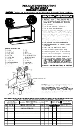
1. MOUNTING: This unit may be surface wired or mounted
over a J-box. Install two fasteners into the keyway mount-
ing holes
h
. Install a third fastener into the lower center
hole. For surface wiring, a 7/8" diameter pre-notched
cutout is provided on one side of the housing
a
. This
cutout should be removed by sawing.
Note: For surface mount with rigid conduit use 1 3/8" flat
washer (provided) to support inside wall of conduit entry
knockout. Insert conduit coupling into knockout. From
inside of housing
a
slide flatwasher over coupling
threads flush to housing wall. Secure with conduit fitting
locknut.
2. LAMP HEAD ASSEMBLY: Select head location and plug
all unused holes with hole plugs
d
provided. Place
swivel
l
in selected housing mounting hole. Locate stop
washer
n
on swivel with index tabs facing toward lamp
head. Screw lock nut
o
onto swivel finger until lamp
head is in desired position. Lamp head can be adjusted
on swivel by loosening swivel screw, setting lamp
position, and tightening swivel to lock in position.
WIRING
1. Connect AC input leads as follows:
120V AC - BLACK AND WHITE TRANSFORMER LEADS
277V AC - BROWN, OR ORANGE AND WHITE TRANS-
FORMER LEADS
Note: Unused lead must be properly insulated with
wirenut or other approved method.
2. ELU4 and ELU8: Connect lamp head leads to charger
board
c
(see Fig. 3). Remote lamp head(s) are con-
nected using remote lamp leads supplied in prepack.
Connect remote lamp leads to charger board
c
. Connect
stripped end of leads to remote leads using wirenut or
other approved method.
ELU4N: Connect lamp head leads to terminal board
e
(see Fig. 2). Remote lamp head(s) must be connected to
screw terminals on terminal board
e
.
3. ELU4N: Connect charger board
c
lead(s) to terminal
board (see Fig. 2).
4. Place battery
k
in housing
a
on battery chassis
q
.
Connect remaining battery and charger board leads as
shown in (Fig. 2 for ELU4N) (Fig. 3 for ELU4 and ELU8).
CAUTION: Be sure red lead is connected to positive
terminal and blue lead is connected to negative terminal
(ELU4 and ELU8 only).
CAUTION: Damage to battery will occur if battery is
connected to charger board for a prolonged period of time
without AC power provided.
5. Close front
b
by placing closure screw
i
in housing
slot
p
, and tighten screw into clip
j
.
Figure 2
Wiring Diagram
ELU4N Only
Page 2
OR ORANGE


