background image

0798

Page O-7

R

MAINTENANCE CONT...

V-BELT CARE:

V-belts may be the item most overlooked during equipment maintenance, but proper care and
maintenance of V-belts and their sheaves (pulleys) can yield great rewards.  The nature of V-
belts makes preventive maintenance relatively easy.  V-belts and sheaves wear gradually and
usually give advance warning of failure.

Nonetheless, it is important to recognize the warnings.  All belts and sheaves will wear as part of
their lifes cycle.  As wear occurs, the belts will ride lower in the grooves.  A worn belt is, in effect,
longer than a new one.

V-belts grip by wedging in the pulley grooves.  Belts that are too loose cause slippage, loss of
power, loss of speed and rapid wear to both the belt and the sheave.  A howl or squeal indicates
that the belt is too loose or the load is too heavy.

ALIGNMENT AND TENSION:

Check to be sure sheaves are properly aligned because misalignment can cause excessive
wear to the belt sidewall.  Unusual wear of the belt outer cover is an indication of more serious
mechanical trouble.  V-belts are designed to operate by making clean, dry surface contact with
the sidewall of the sheaves.  Inspect belts periodically to assure that they are not contaminated
with grease or oil.  Don't allow mud, rust or any other foreign matter to build up in sheave grooves.
Clean sheaves carefully  with a wire brush.

SIGNS OF TROUBLE:

Don't install new V-belts without carefully inspecting the sheaves.  Focus special attention on
these conditions: ~ worn groove sidewalls ~ a shiny sheave groove bottom ~ wobbling sheaves
or ~ damaged sheaves.  Sheave sidewalls must be perfectly straight because the wedging ac-
tion of the V-belt is impaired and its gripping power is reduced when the walls are worn or dished
out.  A shiny sheave groove bottom is an indication that the belt, sheave or both are badly worn
and the belt is bottoming in the groove.  This condition may first be evident on the smaller sheave.

Sheave wobble may be caused by ~ improper installation on the shaft ~ a worn/damaged bush-
ing ~ a worn/damaged sheave hub or by ~ a bent shaft.  Any of these conditions will cause early
failure.  The wobbling
sheave whips the belt
from side to side,
subjecting the belt to
lateral strain and causing
rapid wear to both the
sheave and belt.  Vibration
is another indication of an
improperly installed or
damaged sheave; however,
vibration can also be caused by a damaged belt.

Summary of Contents for Kwik-Trench KT200B

Page 1: ...BOX 840 2009 S HOUSTON LIVINGSTON TEXAS 77351 PH 936 327 3121 FAX 936 327 4025 Web www littlebeaver com E Mail sales littlebeaver com R MFG BY LBEQUIPMENT INC LIVINGSTON TEXASUSA MODEL KT200B 1 800 227 7515 ...

Page 2: ...esigned for user repair with ordinary hand tools No special tools are required Consult the appropriate section of the parts manual for instruc tions Service or technical consulation is available free of charge from the factory in Livingston Texas We will be pleased to help you with any problems or questions Just write fax or call Our hours are 8 00am 4 30pm central time Monday thru Friday Factory ...

Page 3: ...press warranty Implied warranties including those of merchantability and fitness for a particular purpose are limited to 1 year from purchase and to the extent permitted by law Any and all implied warranties are excluded This is the exclusive remedy and liability for consequential damages under any and all warranties are excluded to the extent exclusion is permitted by law Notice Engines are warra...

Page 4: ... 5 Safety Instructions O 6 Maintenance and Lubrication Clutch O 7 Maintenance and Lubrication V Belt O 8 Maintenance and Lubrication V Belt Cutter Hub Bearing O 9 Assembly O 10 Trenching Instructions PARTS MANUAL Page P 1 2 Frame Assembly P 3 Clutch Cutter Hub Assembly P 4 Cutter Wheel Assembly Inside Back Cover Torque Information and Conversion Chart Page ...

Page 5: ...t and Clothing away from moving parts while engine is running 7 KEEP All safety shields and devices in place 8 MAKE Certain everyone is clear before operating the machine 9 DO NOT Drop trencher off the back of a vehicle Trencher s weight can exceed 350 lbs 10 WEAR SAFETY GLASSES 11 KEEP Bystanders at least 10 feet away from work area 12 SHUT OFF Engine and disconnect spark plug wire to adjust serv...

Page 6: ...k plug wire to adjust service refuel or clean the machine Accidental engine starting is possible by rotating the cutter wheel ALL nuts fasteners and fittings must be kept properly torqued After every 25 hours of use the engine nuts and bolts should be checked and tightened if necessary Add lock tight to bolt threads AIR FILTER The air filter needs to be cleaned every 10 hours More often in dusty d...

Page 7: ... surface contact with the sidewall of the sheaves Inspect belts periodically to assure that they are not contaminated with grease or oil Don t allow mud rust or any other foreign matter to build up in sheave grooves Clean sheaves carefully with a wire brush SIGNS OF TROUBLE Don t install new V belts without carefully inspecting the sheaves Focus special attention on these conditions worn groove si...

Page 8: ...ve guards and shields CUTTER HUB REMOVING THE CUTTER HUB Should it ever be necessary to remove the cutter hub remove the three 3 cap screws and insert two 2 1 4 20 cap screws into the threaded holes in the bushing flange Tighten the cap screws alternately and evenly so the press against the shoulder of the cutter hub jacking the bushing from the hub INSTALLING THE CUTTER HUB To install the cutter ...

Page 9: ...ing adjustments on the trencher the spark plug must be disconnected to prevent accidental starting of the engine When determining which teeth are right hand or left hand stand in the operating position stand ing behind the push handle and facing the direction of travel The teeth that are on the right hand side of the blade are the RIGHT TEETH The teeth that are on the left hand side of the blade a...

Page 10: ... Push trencher forward to end of your trench Raise the blade by turning crank handle clockwise until cutting blade is completely out of the ground Stop the engine and turn the fuel off before moving the machine DO NOT use disc blade trenchers with missing teeth If you do this will increase the possibility of engine vibration NOTE If in hard ground roots and other problem areas DO NOT try and force...

Page 11: ...PARTS INFORMATION NOTES ...

Page 12: ...R 0699 Page P 1 1 2 3 2 4 5 6 7 9 9 10 12 I 13 14 15 19 32 15 15 27 33 8 20 11 30 28 21 23 31 38 22 36 18 15 29 16 24 25 16 30 19 37 35 26 35 FRAME ASSEMBLY KT200B 34 ...

Page 13: ... 1 15 KT021 Bolt Carriage 1 4 x 3 4 11 16 30204 Nut Hex 1 4 NC Nylon Lock 6 18 6533 Bolt Hex 1 2 x 2 1 2 NC Gr 5 1 19 9026 KEP Nut Hex 1 4 NC KEP 7 20 KT250 Swivel Rear 1 21 36221 Washer Thrust 1 32 2 22 36223 Washer Thrust 3 32 1 23 KT040 Roll Pin 1 4 x 1 1 2 1 24 KT265 Pin Lock 1 25 KT039 Roll Pin 3 16 x 1 1 26 KT278 Angle Actuator Mounting R H 1 27 KT279 Angle Actuator Mounting L H 1 28 KT283 B...

Page 14: ... 3 21 20 2 11 9 10 19 17 15 6 12 13 1 4 7 5 16 8 12 18 R 0699 Page P 3 23 22 22 24 See page O 7 of this manual for Drive Belt information and instructions BELT DRIVE ASSEMBLY KT200B 1 B F D C A E D G 23 22 ...

Page 15: ...Bar PTO Shaft 1 OD x 12 long 1 7 KTP205 Bearing 1 Pillow Block 2 8 KT219 Bar Pillow Block 2 9 KT001 Bushing SDS 3 4 Pulley w Cap Screws 1 10 9021 Screw Set Socket Head 1 4 x 1 4 NC 2 11 KT043 Pulley 5 6 Diameter 3 Belt 1 12 KT230 Key PTO Shaft 2 13 KT217 Shroud Pulley 1 14 30204 Nut Hex 1 4 NC Nylon Lock 4 15 9024 BP Bolt Hex 1 4 x 1 NC Gr 5 4 16 6533 Bolt Hex 1 2 x 2 1 2 Gr 5 4 17 30153 Washer Fl...

Page 16: ...T4 1031 Spring Die 2 3 KT4 1017 Friction Plate 1 4 KT4 1029 Clutch Facing 2 5 KT4 1026 Nylon Bearing 1 6 KT4 1040 Cap Screw Socket Hd 5 16 x 1 1 2 3 7 KT231 Motor Key 1 8 KT003 Bushing 1 Bore P1 1 1 9 KT4 1016 Cutter Hub 1 7 9 4 8 6 5 1 2 3 4 CutterWheelcollarshould facetheengine Seepagesfollowingfor cutterwheel information ...

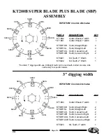
Page 17: ... ROTATION Counter Clockwise PART DESCRIPTION QTY To obtain 1 digging width use 8 Straight teeth 4 Curved teeth bolted on same side call factory for specific details KT19S3 Cutter Wheel 3 width 1 KTSBP SR Tooth Straight Right 2 KTSBP SL Tooth Straight Left 2 KTSBP CIL Tooth Curved in Left 2 KTSBP CIR Tooth Curved in Right 2 KTSBP COL Tooth Curved out Left 2 KTSBP COR Tooth Curved out Right 2 KTS023...

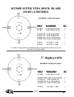
Page 18: ...KTR022 Kit Teeth 2 width 1 SXSR SXSL SXCIR SXCIL To obtain 1 digging width use 2 Straight teeth 2 Curved teeth bolted on same side call factory for specific details R 1099 Page P 7 PART DESCRIPTION QTY KT19R3 Cutter Wheel 3 width 1 KTSXRT COR Tooth Curved out Right 1 KTSXRT SL Tooth Straight Left 1 KTSXRT SR Tooth Straight Right 1 KTSXRT CIL Tooth Curved in Left 1 KTR023 Kit Teeth 3 width 1 SXCOR ...

Page 19: ...ys Note If one belt needs replaced all three belts need to be replaced at the same time to assure maximum performance 4 When belts are in place replace spacer C and re tighten belt adjustment nuts until there is little slack in the belts D 5 If the digger blade slips when trenching add more tension to the belts However over tensioning will cause premature belt and or bearing failure A C D B BELT R...

Page 20: ...P O BOX 840 LIVINGSTON TEXAS 77351 PH 409 327 3121 FAX 409 327 4025 Web www littlebeaver com E Mail sales littlebeaver com R THINK SAFETY FIRST ...

Reviews: