31
•
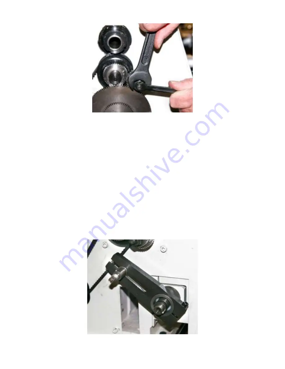
To change a gear in positions B or C, use an 8 mm end wrench on the square end of the shaft
to keep it from turning. Loosen the nut with a 19 mm end wrench and remove the notched
washer from behind the nut. Remove the nut so you can slide the gear off the shaft.
The B and C gears ride on a sleeve that is free to turn on the shaft. It has a keyway and key
that keep the B and C gears turning together. Lubricate this sleeve every time you change a B
or C gear. Bad things happen when these sleeves seize on the shaft.
•
To change the gear in position D, use a 17 mm end wrench to remove the shoulder bolt that
retains the gear. Gear position D has a spacer behind the gear. When you only use three gears,
put the spacer outside the gear so the gear will align with the gear in position B.
In the change gear tables, some
combinations have “Any” in column C.
For these combinations,
you can use any gear for position C; this gear acts only as a spacer and does not engage the other
gears. Position B is an idler and does not affect the overall gear ratio. The table shows a gear that
makes it easy to properly engage the gears, although you can use any gear in position B as well.
The B-C Gear shaft is mounted on an arm that pivots around the lead screw. You can move the B-
C shaft location to engage different gear combinations. To engage a new set of gears, use a 5 mm
hex wrench to loosen the socket head cap screw that locks the B-C arm around the lead screw.
Use an 8 mm end wrench on the square end of the B-C shaft to loosen it in the slot in the arm.
Move the gears so they are all in engagement. Tighten the arm around the lead screw and tighten
the B-C shaft.
Summary of Contents for HiTorque 7500
Page 40: ...40 Parts Diagram 7500 Model 7500 drawing 1...
Page 41: ...41 Model 7500 drawing 2...
Page 42: ...42 Parts Diagram 7550 Model 7550 drawing 1...
Page 43: ...43 Model 7550 drawing 2...
Page 47: ...47 Wiring Diagram...


