2-109
January 24, 2017
Removal and Installation
CLG835H
Removal and installation of fuel tank
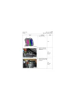
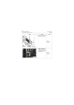
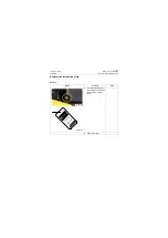
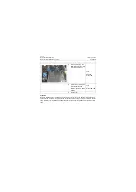
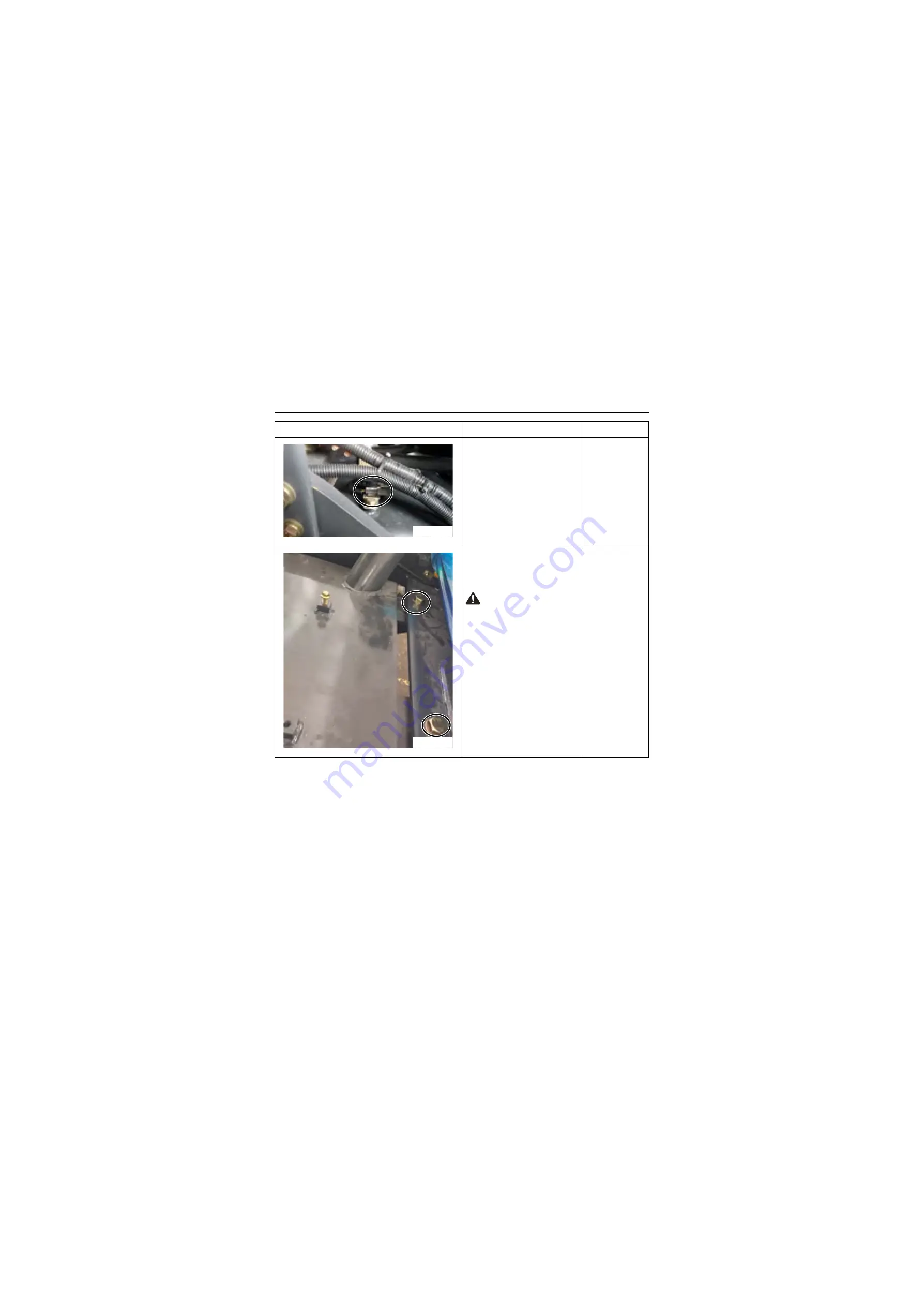
4. Removal of fuel sensor wire
harness:
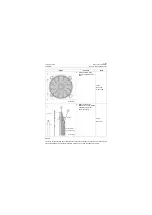
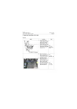
Remove the harness con-
nector of fuel tank sensor.
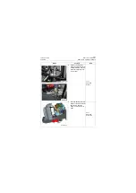
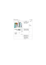
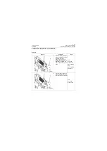
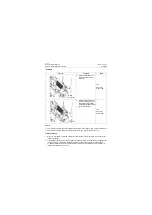
5. Removal of fuel tank:
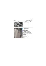
Remove the 4 mounting
bolts and nuts from the fuel
tanks.
Caution: Fuel tank is
connected to frame
through bolts and nuts in four
mounting points. After mount-
ing bolts are loosened, fuel
tank will separate from frame.
Before removal, use a reliable
tool (e.g., forklift) with suffi-
cient bearing capacity to sup-
port fuel tank.
Before step 5, make sure
steps 2~4 have been done;
otherwise, corresponding
parts will be damaged, and
even a safety accident will
occur.
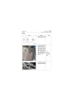
Tool:
Open-end
wrench 30#,
Carrier tool or
tooling
Graph
Contents
Tools
P18P00197
P18P00198
Summary of Contents for CLG835H
Page 2: ......
Page 4: ...Contents January 24 2017 CLG835H...
Page 6: ...1 2 General Information January 24 2017 CLG835H...
Page 38: ...1 34 Machine Inspection Table January 24 2017 CLG835H...
Page 156: ...3 2 Power Train System January 24 2017 CLG835H...
Page 214: ...3 2 Power Train System January 24 2017 CLG835H...
Page 272: ...3 60 Testing and adjustment January 24 2017 Power Train Test CLG835H...
Page 276: ...4 4 Hydraulic System January 24 2017 CLG835H...
Page 552: ...6 2 Driver s Cab System January 24 2017 CLG835H...
Page 608: ...7 2 Structure January 24 2017 CLG835H...
Page 662: ...8 4 Electrical System January 24 2017 CLG835H...
Page 677: ...8 19 January 24 2017 Structure Function Principle CLG835H Power System P18E00014...

