3-36
Removal and Installation
January 24, 2017
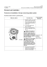
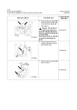
Removal and installation of torque converter-gearbox system
CLG835H
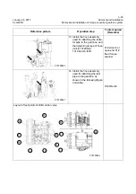
Logic diagram of test points and gear clutch
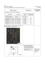
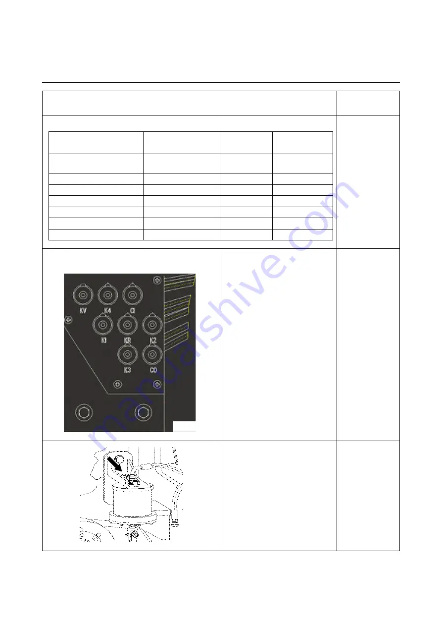
Mapping diagram of centralized measuring point
mounting plate and measuring point
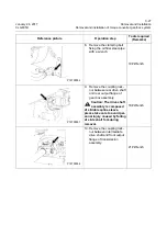
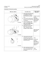
15. Install the hose assembly
used for attaching emer-
gence parking brake cham-
ber to the brake system, the
tightening torque is
37±2Nm\ 27.29±1.48 lbf•ft.
24# wrench or
open-end 24#
fixed torque
spanner
Reference picture
Operation step
Tools required
(Remarks)
Decal marker
Meanings
Theoretical
value
S/N in the corre-
sponding valve
PRESSURE OF IN FRONT
OF THE CONVERTER
Inlet pressure of torque
converter
Opening pres-
sure: 1.1 MPa
51
PRESSURE OF KV CLUTCH KV clutch pressure
1.6-1.8MPa
53
PRESSURE OF KR CLUTCH KR clutch pressure
1.6-1.8MPa
55
PRESSURE OF K1 CLUTCH
K1 clutch pressure
1.6-1.8MPa
56
PRESSURE OF K2 CLUTCH
K2 clutch pressure
1.6-1.8MPa
57
PRESSURE OF K3 CLUTCH
K3 clutch pressure
1.6-1.8MPa
58
PRESSURE OF K4 CLUTCH
K4 clutch pressure
1.6-1.8MPa
59
P18T00063
P18T00064
Summary of Contents for CLG835H
Page 2: ......
Page 4: ...Contents January 24 2017 CLG835H...
Page 6: ...1 2 General Information January 24 2017 CLG835H...
Page 38: ...1 34 Machine Inspection Table January 24 2017 CLG835H...
Page 156: ...3 2 Power Train System January 24 2017 CLG835H...
Page 214: ...3 2 Power Train System January 24 2017 CLG835H...
Page 272: ...3 60 Testing and adjustment January 24 2017 Power Train Test CLG835H...
Page 276: ...4 4 Hydraulic System January 24 2017 CLG835H...
Page 552: ...6 2 Driver s Cab System January 24 2017 CLG835H...
Page 608: ...7 2 Structure January 24 2017 CLG835H...
Page 662: ...8 4 Electrical System January 24 2017 CLG835H...
Page 677: ...8 19 January 24 2017 Structure Function Principle CLG835H Power System P18E00014...

