3-55
January 24, 2017
Removal and Installation
CLG835H
Removal and installation of rear axle assembly
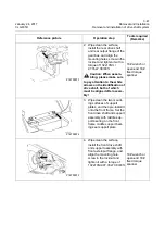
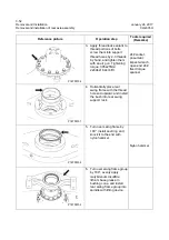
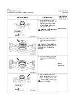
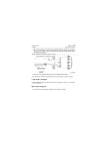
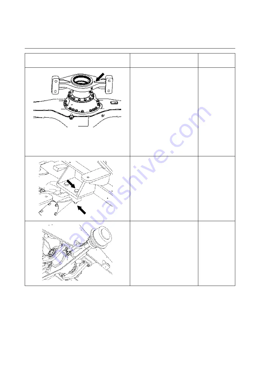
15. Evenly apply the molybde-
num disulfide lithium base
grease to bushing cone, and
then lift and install the front
swing support subassembly
onto the bearing seat of the
main transmission.
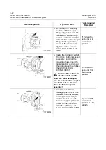
16. Place the axle assembly on
a transport device with a lift-
ing device, and right under
mounting point of rear axle.
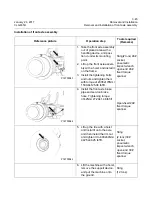
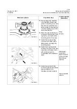
17. Install the axle assembly
onto the rear frame with a
lifting device and align the
mounting holes.
Sling
(2 tons)
18. Install the mounting bolts,
washers and nuts of the axle
assembly and tighten them
with an blower gun to
1122±90Nm\ 827.28±66.38
lbf•ft.
36# socket,
pneumatic
impact wrench,
open-end 36#
fixed torque
spanner
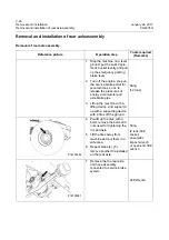
19. Install the axle and hose
connecting the service brake
pipe and tighten it to
37±2Nm\ 27.29±1.48 lbf•ft.
Open-end 24#
wrench
Reference picture
Operation step
Tools required
(Remarks)
P18T00118
P18T00119
P18T00120
Summary of Contents for CLG835H
Page 2: ......
Page 4: ...Contents January 24 2017 CLG835H...
Page 6: ...1 2 General Information January 24 2017 CLG835H...
Page 38: ...1 34 Machine Inspection Table January 24 2017 CLG835H...
Page 156: ...3 2 Power Train System January 24 2017 CLG835H...
Page 214: ...3 2 Power Train System January 24 2017 CLG835H...
Page 272: ...3 60 Testing and adjustment January 24 2017 Power Train Test CLG835H...
Page 276: ...4 4 Hydraulic System January 24 2017 CLG835H...
Page 552: ...6 2 Driver s Cab System January 24 2017 CLG835H...
Page 608: ...7 2 Structure January 24 2017 CLG835H...
Page 662: ...8 4 Electrical System January 24 2017 CLG835H...
Page 677: ...8 19 January 24 2017 Structure Function Principle CLG835H Power System P18E00014...

