3-18
Structure Function Principle
January 24, 2017
Drive Shaft System
CLG835H
Drive Shaft System
In the wheel loader, the drive shaft system is mainly used to deliver the power between the two con-
nected shafts, of which the relative position changes constantly during operation. Because of the special
transmission characteristics of universal joint, the drive shaft may connect two transmission parts with
nominal concentric axial line. However, an error may occur during installation and axial line deviates
from the original position when operating, the drive shaft is widely used in shoveling transportation
machine.
System composition and position
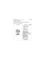
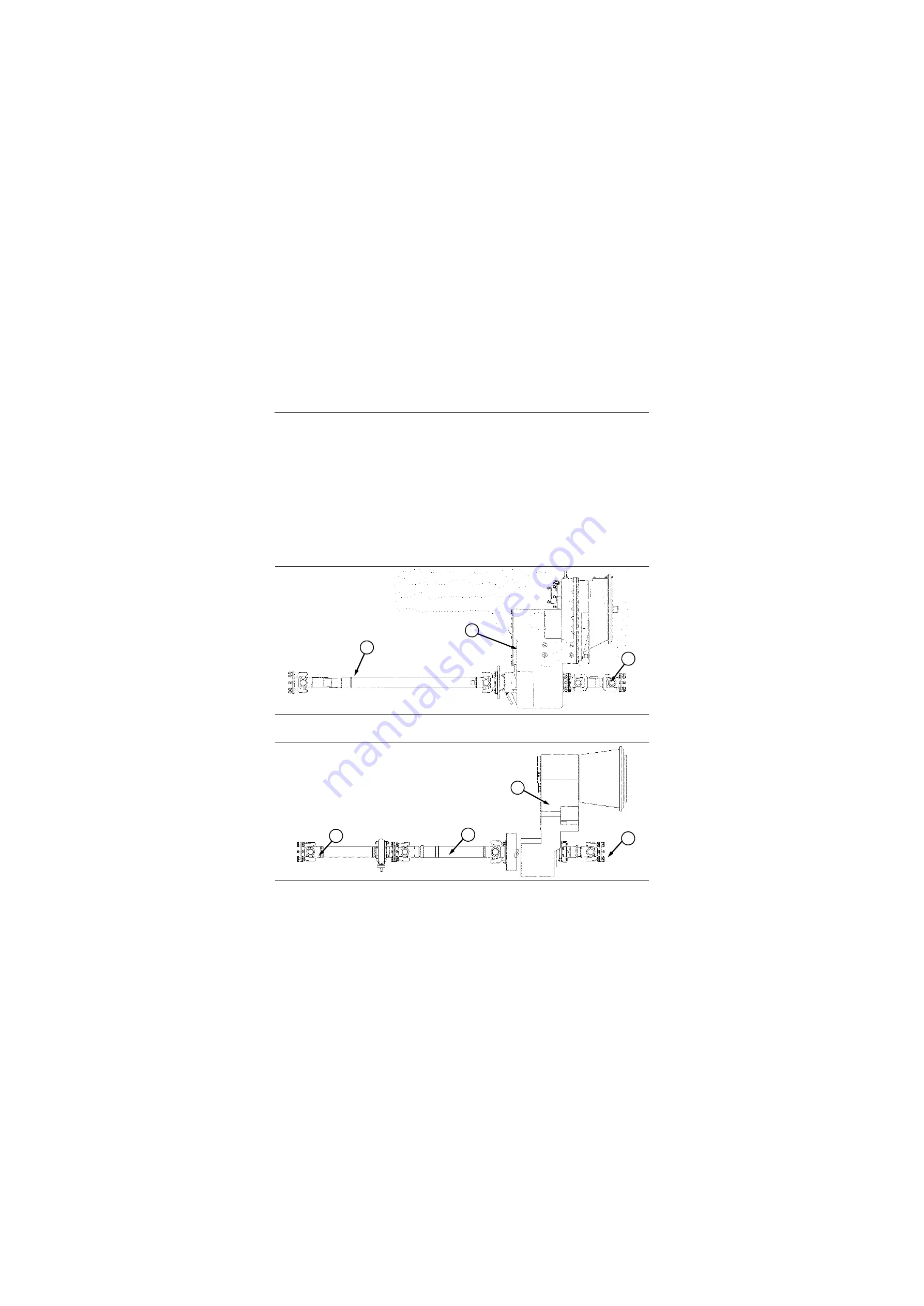
The drive shaft system of wheel loader is composed by the following two structural types in accordance
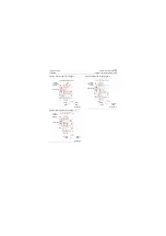
with its formal layout, the drive shaft system shown in Figure 3-25 consists of rear and front drive shafts,
the one shown in Figure 3-26 consists of rear, front, intermediate shafts and support assembly.
Figure 3-22 Drive shaft system
1. Front drive shaft
2. Torque converter-gear box assembly
3. Rear drive shaft
Figure 3-23 Drive shaft system
1. Front drive shaft&support assembly
2. Intermediate drive shaft
3. Torque converter-gear box assembly
4. Rear drive shaft
P18T00022
3
2
1
P18T00023
1
2
3
4
Summary of Contents for CLG835H
Page 2: ......
Page 4: ...Contents January 24 2017 CLG835H...
Page 6: ...1 2 General Information January 24 2017 CLG835H...
Page 38: ...1 34 Machine Inspection Table January 24 2017 CLG835H...
Page 156: ...3 2 Power Train System January 24 2017 CLG835H...
Page 214: ...3 2 Power Train System January 24 2017 CLG835H...
Page 272: ...3 60 Testing and adjustment January 24 2017 Power Train Test CLG835H...
Page 276: ...4 4 Hydraulic System January 24 2017 CLG835H...
Page 552: ...6 2 Driver s Cab System January 24 2017 CLG835H...
Page 608: ...7 2 Structure January 24 2017 CLG835H...
Page 662: ...8 4 Electrical System January 24 2017 CLG835H...
Page 677: ...8 19 January 24 2017 Structure Function Principle CLG835H Power System P18E00014...


