3-37
January 24, 2017
Removal and Installation
CLG835H
Removal and installation of drive shaft system
Removal and installation of drive shaft system
Removal of drive shaft system
Reference picture
Operation step
Tools required
(Remarks)
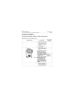
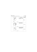
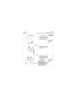
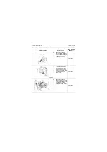
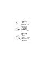
1. Park the machine on a level
ground, turn off the engine,
and place the gear box han-
dle in neutral position, pull
up the emergency parking
brake lever and place the
wedges.
Caution: The drive shaft
assembly is composed
of slidable spline sleeve,
please take care to avoid per-
sonal injury caused by falling
of slide shaft fork during
removal.
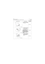
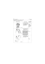
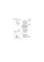
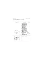
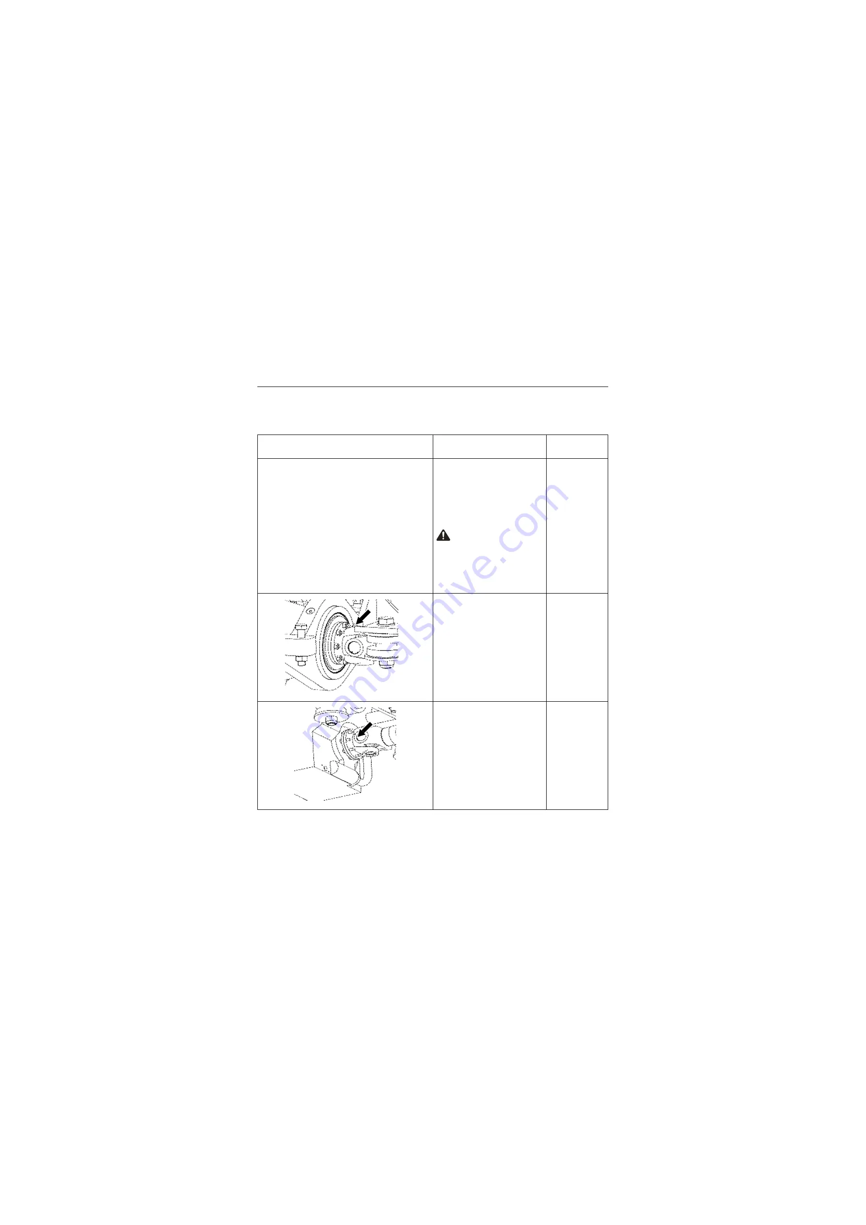
2. Remove the connecting
locknut between the rear
drive shaft and rear axle
input flange with a wrench.
18# Wrench
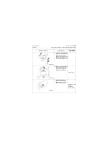
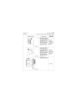
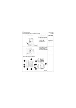
3. Remove the connecting
locknut between rear drive
shaft and rear output flange
of gear box with a wrench,
and place the rear drive
shaft assembly in a safe
area.
18# Wrench
P18T00065
P18T00066
Summary of Contents for CLG835H
Page 2: ......
Page 4: ...Contents January 24 2017 CLG835H...
Page 6: ...1 2 General Information January 24 2017 CLG835H...
Page 38: ...1 34 Machine Inspection Table January 24 2017 CLG835H...
Page 156: ...3 2 Power Train System January 24 2017 CLG835H...
Page 214: ...3 2 Power Train System January 24 2017 CLG835H...
Page 272: ...3 60 Testing and adjustment January 24 2017 Power Train Test CLG835H...
Page 276: ...4 4 Hydraulic System January 24 2017 CLG835H...
Page 552: ...6 2 Driver s Cab System January 24 2017 CLG835H...
Page 608: ...7 2 Structure January 24 2017 CLG835H...
Page 662: ...8 4 Electrical System January 24 2017 CLG835H...
Page 677: ...8 19 January 24 2017 Structure Function Principle CLG835H Power System P18E00014...

