3-40
Removal and Installation
January 24, 2017
Removal and installation of drive shaft system
CLG835H
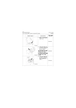
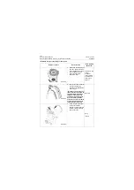
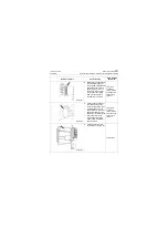
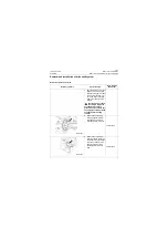
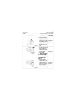
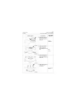
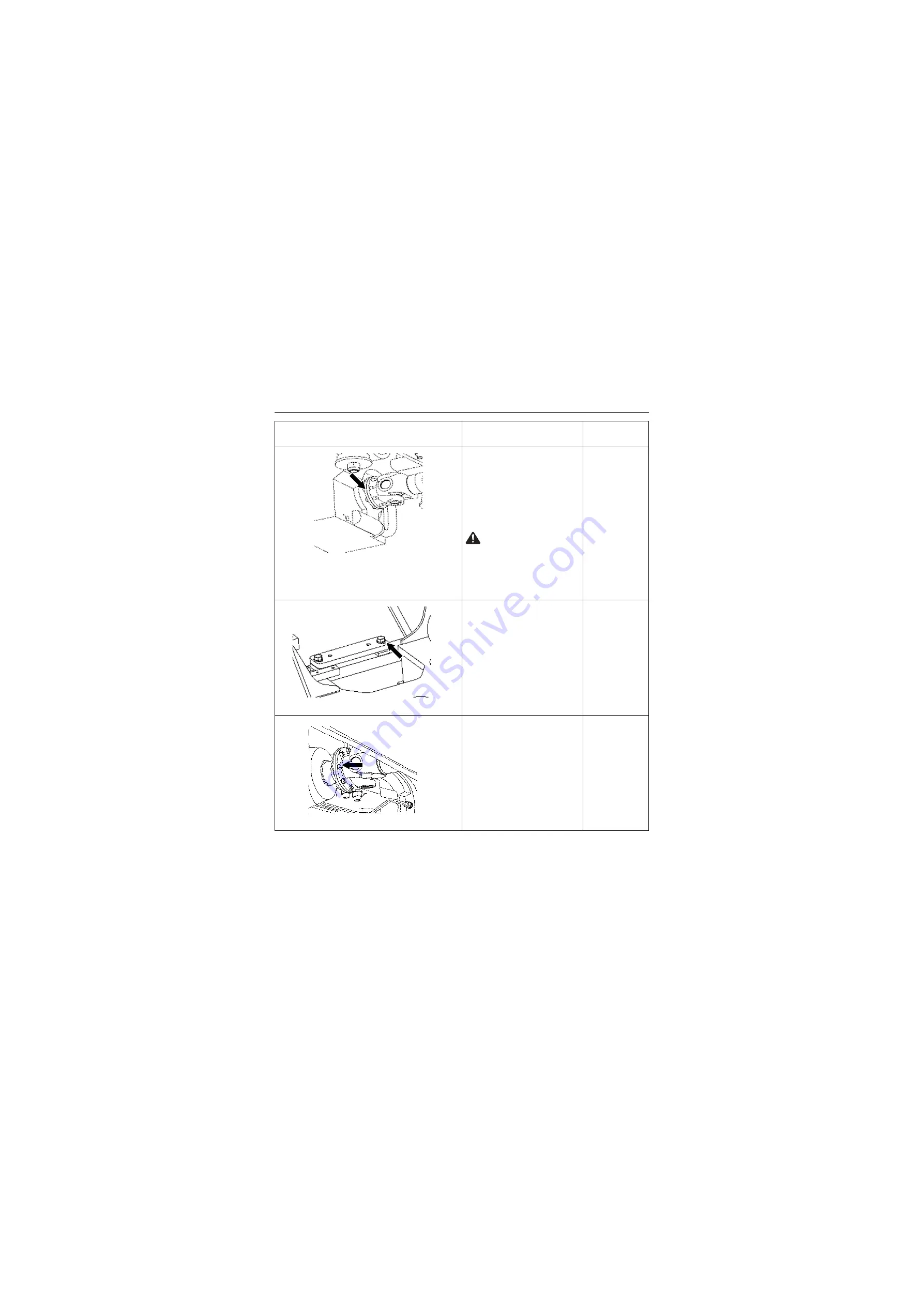
2. Wipe clean the surface,
install the rear drive shaft
and rear output flange of the
gear box, and align the
mounting holes, screw in the
locknut and tighten it with a
torque of 132±10Nm\
97.35±7.38 lbf•ft.
Caution: When assem-
bling, please make sure
to pay attention to the white
arrows on the identification of
drive shaft, both of which
must be aligned after assem-
bly!
18# wrench or
open-end 18#
fixed torque
spanner
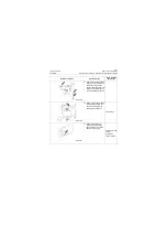
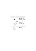
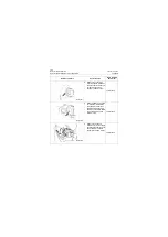
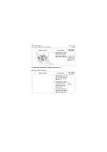
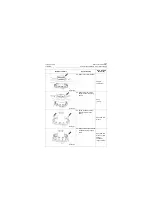
3. Wipe clean the two mount-
ing surfaces of support
plates, and then pre-install it
onto the front frame. Set the
front drive shaft and support
assembly with middle sup-
port bearing on the front
frame middle support bear-
ing seat support plate.
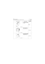
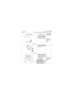
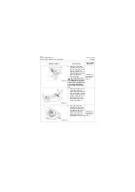
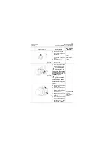
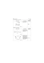
4. Wipe clean the surface,
install the front drive shaft
and support assembly with
front axle input flange, and
align the mounting hole,
screw in the locknut and
tighten it with a torque of
132±10Nm\97.35±7.38 lbf•ft.
18# wrench or
open-end 18#
fixed torque
spanner
Reference picture
Operation step
Tools required
(Remarks)
P18T00073
P18T00074
P18T00075
Summary of Contents for CLG835H
Page 2: ......
Page 4: ...Contents January 24 2017 CLG835H...
Page 6: ...1 2 General Information January 24 2017 CLG835H...
Page 38: ...1 34 Machine Inspection Table January 24 2017 CLG835H...
Page 156: ...3 2 Power Train System January 24 2017 CLG835H...
Page 214: ...3 2 Power Train System January 24 2017 CLG835H...
Page 272: ...3 60 Testing and adjustment January 24 2017 Power Train Test CLG835H...
Page 276: ...4 4 Hydraulic System January 24 2017 CLG835H...
Page 552: ...6 2 Driver s Cab System January 24 2017 CLG835H...
Page 608: ...7 2 Structure January 24 2017 CLG835H...
Page 662: ...8 4 Electrical System January 24 2017 CLG835H...
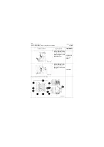
Page 677: ...8 19 January 24 2017 Structure Function Principle CLG835H Power System P18E00014...

