4-20
Structure Function Principle
January 24, 2017
Work hydraulic system
CLG835H
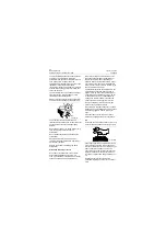
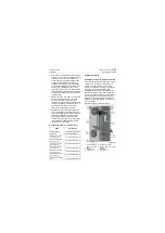
In which, the oil return chamber is used to
temporarily store the hydraulic oil that returns
from the system to effectively reduce the back-
flow velocity so as to avoid bubbles in the
hydraulic oil tank resulted from too fast oil return.
The oil return filter mainly filters the oil returning
to the hydraulic oil tank to prevent pollutant from
entering into the system through the oil tank to
cause pollution. The baffle is used to form
isolation circulation for cold and hot oil in the oil
tank to prevent oil shake from generating large
quantities of bubbles and isolate oil suction port
from oil return port to ensure gas separates out
of hydraulic oil return. Washing port is used to
clean the dirt in the oil tank. Oil drain hole is used
to drain fluid out of oil tank when replace oil or
clean oil tank. Oil suction port is used to supply
oil for hydraulic pump. The ventilated oil conduit
is used for exhalation of a breather and to lead
the oil vapor exhaled by the breather to
underbody. Hydraulic oil is filled from the oil filler
after filtration by the oil filter vehicle. Oil filler filter
element is used to prevent large particles from
entering into oil tank when replacing and filling
hydraulic oil. The function of the breather is that it
sucks air from atmosphere to fill the air space
when the air pressure in oil tank is negative and
that exhaust extra air to realize the protection
function when the air pressure in oil tank is out of
limit. Oil level gauge is used to observe the oil
level of oil tank. Oil suction port is used to supply
oil for hydraulic pump.
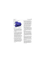
Plunger pump
Main technical parameters
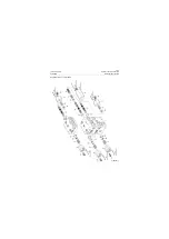
Structure and working principle of plunger
pump
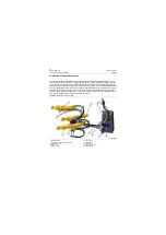
Same pump is used for the plunger pump of work
hydraulic system and that of steering hydraulic
system, that is, work hydraulic system and
steering hydraulic system share one pump. The
plunger pump is located under cab and installed
on the right power take-off of the transmission
and tightened it by stud and nut. It is driven by
engine via torque converter and transmission to
supply oil for work and steering hydraulic system.
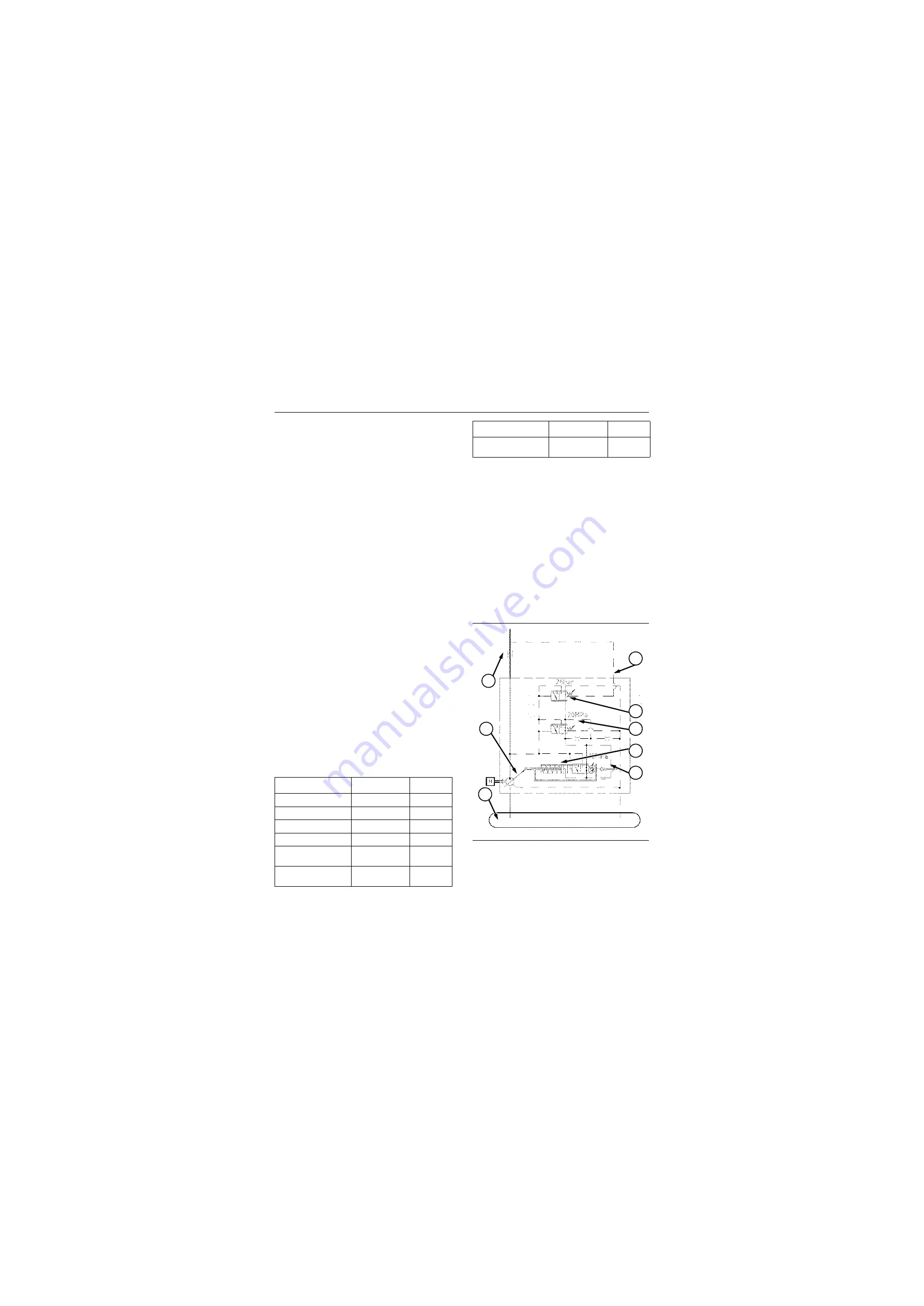
Outline diagram and working principle of
plunger pump:
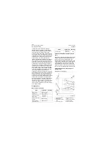
Items
Parameters
Remarks
Rated pressure
19Mpa\ 2755psi
Displacement
100ml/r\ 100cc/r
Direction of rotation
Left rotation
Rated speed
2200rpm
Pressure of the shut-
off valve
20Mpa\ 2900psi
Pressure of flow
compensator valve
2.6Mpa\ 377psi
Operating fluid
Anti-wear
hydraulic oil
46#
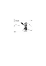
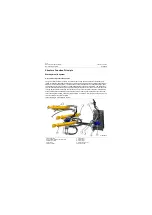
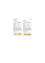
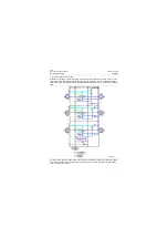
Schematic of working pump
1. Hydraulic oil tank
2. Swashplate
3. Control valve (simpli-
fied)
4. Load sensing port
5. Flow compensation
valve
6. Pressure shut-off valve
7. Variable cylinder
8. Power control valve
Items
Parameters
Remarks
P18H00011
2
3
4
5
7
8
6
1
Summary of Contents for CLG835H
Page 2: ......
Page 4: ...Contents January 24 2017 CLG835H...
Page 6: ...1 2 General Information January 24 2017 CLG835H...
Page 38: ...1 34 Machine Inspection Table January 24 2017 CLG835H...
Page 156: ...3 2 Power Train System January 24 2017 CLG835H...
Page 214: ...3 2 Power Train System January 24 2017 CLG835H...
Page 272: ...3 60 Testing and adjustment January 24 2017 Power Train Test CLG835H...
Page 276: ...4 4 Hydraulic System January 24 2017 CLG835H...
Page 552: ...6 2 Driver s Cab System January 24 2017 CLG835H...
Page 608: ...7 2 Structure January 24 2017 CLG835H...
Page 662: ...8 4 Electrical System January 24 2017 CLG835H...
Page 677: ...8 19 January 24 2017 Structure Function Principle CLG835H Power System P18E00014...

