4-27
January 24, 2017
Structure Function Principle
CLG835H
Work hydraulic system
Installation position and working principle
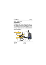
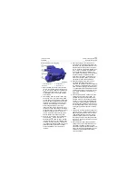
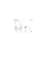
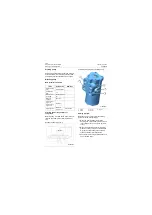
The control valve is installed on the mounting board in front frame. The function of the control valve is to
control moving direction and speed of the bucket cylinder and the boom cylinder by changing the flowing
direction of oil so as to satisfy loader's working requirements under different work conditions.
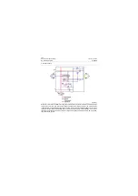
Configuration: whole tandem closed neutral position slide valve;
Oil lines type: cascade and paralleling bucket tilting priority ;
Main components: bucket reversing valve, boom reversing valve, safety valve, pressure compensation
valve, LS relief valve, LS flow controller, etc.
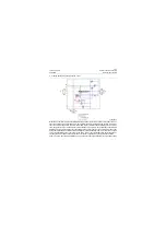
The bucket reversing valve is a three-stack valve, which can control three actions of the bucket, i.e. to
tilting forward, backward and keeping.
The boom reversing valve is a four-stack valve, which can control four actions of the boom, i.e. raising,
keeping, lowering and floating lowering.
The safety valve controls the pressure of system. When the pressure of system exceeds the setting
value, oil will overflow to the oil tank to protect system from being damaged.
Pressure compensation valve, operated in multiple circuit, can guarantee that the flow of main valve can
not be changed by different loads so that the system has the performance of composite operation.
LS relief valve controls the pressure of LS oil line. When the LS pressure exceeds the setting value, oil
will overflow to the oil tank. The pressure of work system is the sum of setting pressure of LS relief valve
and the pump flow control valve in work hydraulic system.
LS flow controller can guarantee that the LS oil line has continuous flow and improve the response
speed of LS oil line.
Back pressure valve increases the oil return pressure at the time of bucket dumping and boom descend-
ing and improves the stability of bucket dumping and boom descending.
Summary of Contents for CLG835H
Page 2: ......
Page 4: ...Contents January 24 2017 CLG835H...
Page 6: ...1 2 General Information January 24 2017 CLG835H...
Page 38: ...1 34 Machine Inspection Table January 24 2017 CLG835H...
Page 156: ...3 2 Power Train System January 24 2017 CLG835H...
Page 214: ...3 2 Power Train System January 24 2017 CLG835H...
Page 272: ...3 60 Testing and adjustment January 24 2017 Power Train Test CLG835H...
Page 276: ...4 4 Hydraulic System January 24 2017 CLG835H...
Page 552: ...6 2 Driver s Cab System January 24 2017 CLG835H...
Page 608: ...7 2 Structure January 24 2017 CLG835H...
Page 662: ...8 4 Electrical System January 24 2017 CLG835H...
Page 677: ...8 19 January 24 2017 Structure Function Principle CLG835H Power System P18E00014...

