


4-42
Structure Function Principle
January 24, 2017
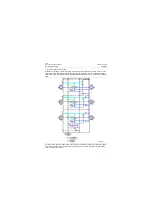
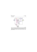
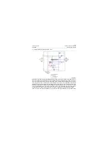
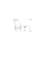
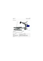
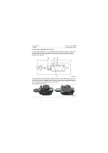
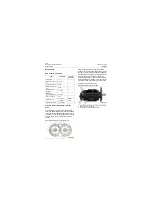
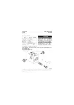
Steering hydraulic system
CLG835H
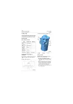
Priority valve
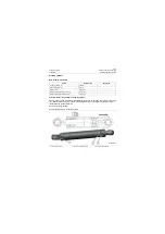
Main technical parameters
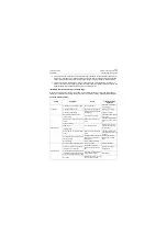
No automatic return
to the neutral posi-
tion of steering
wheel
When the pressure drop in the neu-
tral position increases and steering
wheel stops turning, the metering
pump is not unloaded (vehicle off
tracking occurs)
Steering column axially abuts
the spool to the bottom
Troubleshooting in accor-
dance with specific condi-
tions
High resistance of steering
column
Leaf spring break
The installation of steering
column is not concentric to
that of spool
No steering to the
extreme position
No steering of steering cylinder to
the extreme position, steering is
heavy as reflected
Low pressure of safety valve
Increase the pressure of
safety valve properly
No manual steering
During power steering, the cylinder
piston moves to the extreme posi-
tion, the driver does not have obvi-
ous feel of end point; during manual
steering, the steering wheel rotates
but the cylinder is still
Large radial or axial clearance
of stator and rotor pair
Replace the stator and
rotor pair
Items
Parameters
Service conditions
Remarks
Flux
240L/min\63.4US gpm
Pressure of safety valve
18MPa\2610psi
Operating fluid
Anti-wear hydraulic oil
HM46/HV46
Faults
Symptom
Cause
Troubleshooting
methods
Summary of Contents for CLG835H
Page 2: ......
Page 4: ...Contents January 24 2017 CLG835H...
Page 6: ...1 2 General Information January 24 2017 CLG835H...
Page 38: ...1 34 Machine Inspection Table January 24 2017 CLG835H...
Page 156: ...3 2 Power Train System January 24 2017 CLG835H...
Page 214: ...3 2 Power Train System January 24 2017 CLG835H...
Page 272: ...3 60 Testing and adjustment January 24 2017 Power Train Test CLG835H...
Page 276: ...4 4 Hydraulic System January 24 2017 CLG835H...
Page 552: ...6 2 Driver s Cab System January 24 2017 CLG835H...
Page 608: ...7 2 Structure January 24 2017 CLG835H...
Page 662: ...8 4 Electrical System January 24 2017 CLG835H...
Page 677: ...8 19 January 24 2017 Structure Function Principle CLG835H Power System P18E00014...


