4-54
Structure Function Principle
January 24, 2017
Brake system
CLG835H
Brake valve
Main technical parameters
Structure and working principle of brake
valve
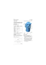
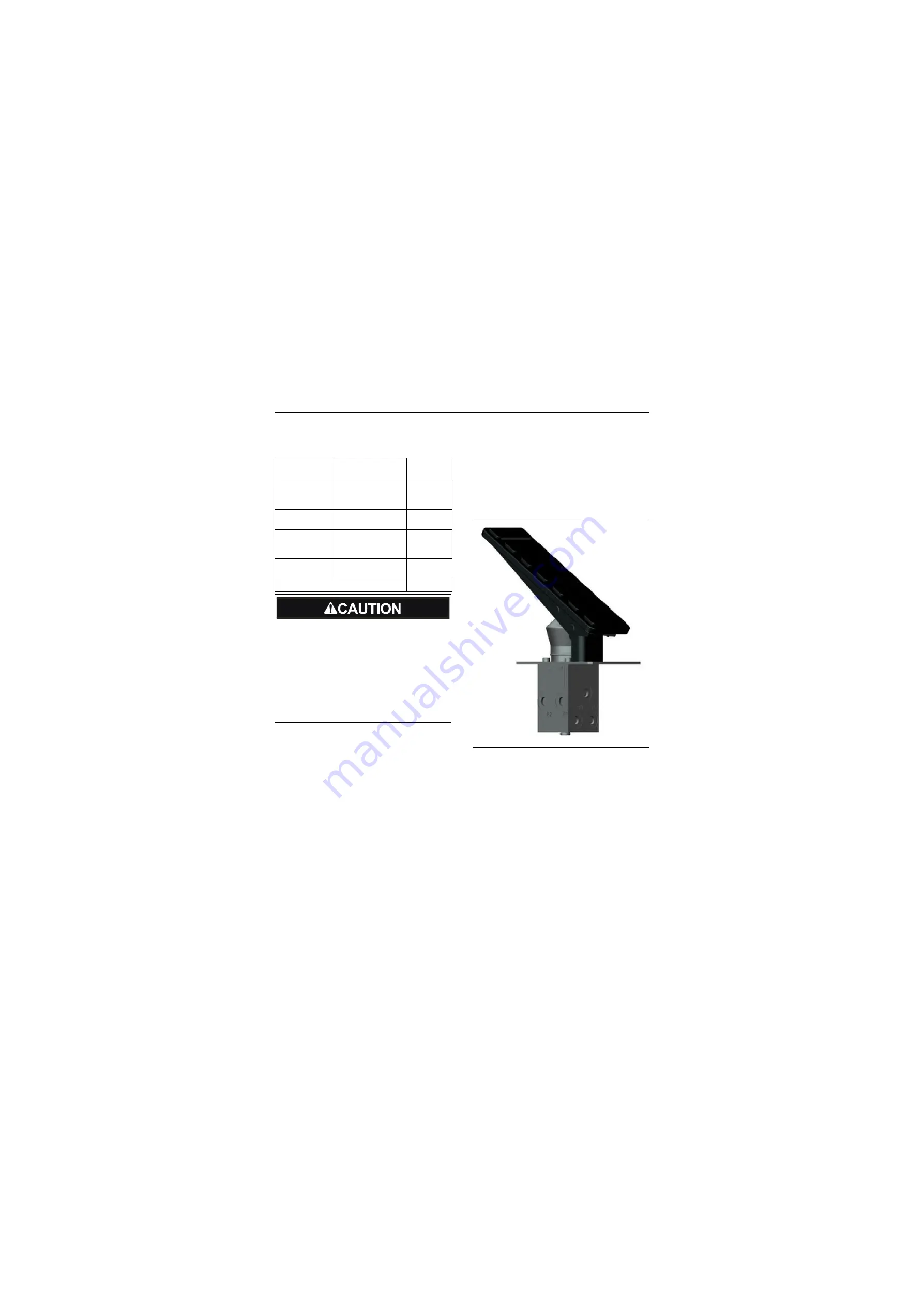
Brake valve (also called foot brake valve) is
located on left floor of cab and its pedal can be
controlled by left foot. Brake valve, which
realizes the sensitive follow-up control during the
brake and release process of service brake
system, is one of the main parts of brake system.
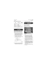
Items
Parameters
Service
conditions
Maximum
allowed system
pressure
21MPa\ 3045psi
\
Maximum brake
pressure
6±0.4MPa\
870±58psi
\
Pedal force
under maximum
pressure (about)
170N\ 38.22lbf
\
Pedal stroke
(about)
20°
\
Operating fluid
Anti-wear hydraulic oil HM46/HV46
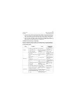
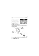
As the structure of dual-circuit brake valve is
complex and the requirement for assembly
and adjustment is high, the removal & instal-
lation and adjustment can not be conducted
by non-professionals without authorization.
Before the dual-circuit brake valve is deliv-
ered, its pressure value has been adjusted. If
fault occurs or the maximum brake pressure
value is wrong, please contact its factory or
dealer.
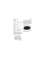
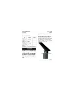
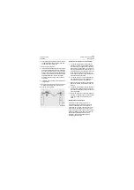
Outline diagram of brake valve
P18H00041
Summary of Contents for CLG835H
Page 2: ......
Page 4: ...Contents January 24 2017 CLG835H...
Page 6: ...1 2 General Information January 24 2017 CLG835H...
Page 38: ...1 34 Machine Inspection Table January 24 2017 CLG835H...
Page 156: ...3 2 Power Train System January 24 2017 CLG835H...
Page 214: ...3 2 Power Train System January 24 2017 CLG835H...
Page 272: ...3 60 Testing and adjustment January 24 2017 Power Train Test CLG835H...
Page 276: ...4 4 Hydraulic System January 24 2017 CLG835H...
Page 552: ...6 2 Driver s Cab System January 24 2017 CLG835H...
Page 608: ...7 2 Structure January 24 2017 CLG835H...
Page 662: ...8 4 Electrical System January 24 2017 CLG835H...
Page 677: ...8 19 January 24 2017 Structure Function Principle CLG835H Power System P18E00014...

