4-62
Structure Function Principle
January 24, 2017
Brake system
CLG835H
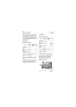
Brake cylinder
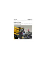
The brake cylinder, as key actuation component for emergency & parking brake system, is installed on
the left side of front end of transmission housing.
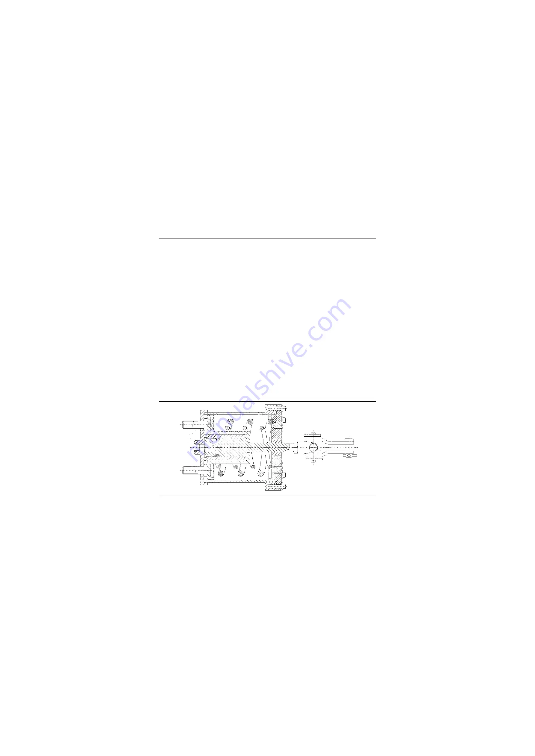
Structural composition and working principle of brake cylinder
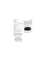
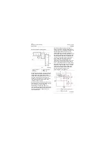
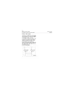
The structure of brake cylinder is shown as below, its working pressure is 15.9MPa\2305.5psi. The dis-
engagement and engagement of emergency & parking brake are available with brake cylinder whose
lever is coupled with cam handle. When the system has no oil pressure or the control knob of emergency
& parking brake is pulled up, no pressure oil enters the left chamber of brake cylinder. The spring seat
and piston are always pushed to the left side by force from spring, pull the parking brake lever to engage
it, thus to achieve the brake performance.
When the system reaches the working pressure, and the control knob of emergency & parking brake is
pressed down, the pressure oil flows into the left chamber of brake cylinder through solenoid valve to
compress the spring, push the spring seat and piston to right side and the parking brake lever so as to
release the brake and drive the vehicle. When the oil pressure of accumulator in the circuit of service
brake is lower than 7MPa\1015psi, the cut-off switch of emergency brake acts to cut off the power of
solenoid valve. The hydraulic oil in the parking brake cylinder returns to oil tank via manual solenoid
valve. Force from spring pushes the spring seat and piston left side and pulls the parking brake lever to
lock the brake, meanwhile, transmission shifts to the neutral position to achieve the emergency parking
of loader.
The machine is equipped with parking brake which is released by hydraulic pressure based on spring
action (working of brake cylinder). If the engine, hydraulic system or the brake system fails, the machine
is braked and unable to drive. When the machine fails to drive and needs to be towed, the pin shaft in the
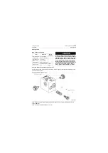
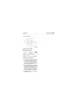
brake cylinder as shown below is removed, tow the machine after the parking brake is released.
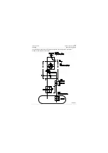
Structure diagram of brake cylinder
P18H00051
P18H00051
Summary of Contents for CLG835H
Page 2: ......
Page 4: ...Contents January 24 2017 CLG835H...
Page 6: ...1 2 General Information January 24 2017 CLG835H...
Page 38: ...1 34 Machine Inspection Table January 24 2017 CLG835H...
Page 156: ...3 2 Power Train System January 24 2017 CLG835H...
Page 214: ...3 2 Power Train System January 24 2017 CLG835H...
Page 272: ...3 60 Testing and adjustment January 24 2017 Power Train Test CLG835H...
Page 276: ...4 4 Hydraulic System January 24 2017 CLG835H...
Page 552: ...6 2 Driver s Cab System January 24 2017 CLG835H...
Page 608: ...7 2 Structure January 24 2017 CLG835H...
Page 662: ...8 4 Electrical System January 24 2017 CLG835H...
Page 677: ...8 19 January 24 2017 Structure Function Principle CLG835H Power System P18E00014...


