4-106
Removal and Installation
January 24, 2017
Work hydraulic system
CLG835H
Removal and Installation
Work hydraulic system
Removal and installation of hydraulic oil tank assembly
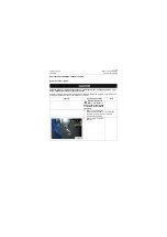
Removal for hydraulic oil tank assembly
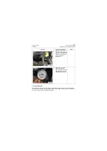
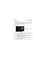
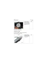
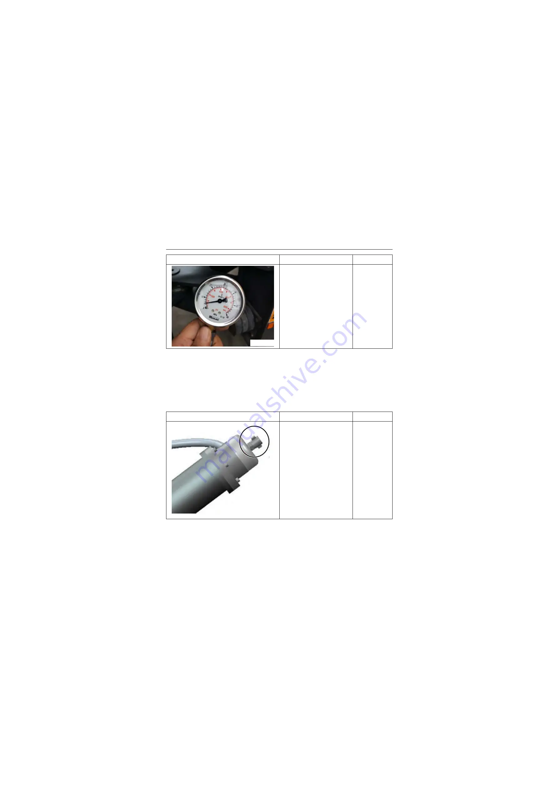
3. Depress the brake pedal
and hold it to the maximum
angle; check the reading of
pressure gauge, which shall
be 6±0.4MPa\ 870±58psi at
this time.
Figures
Operation instruction
Tools
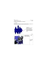
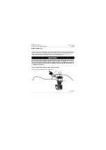
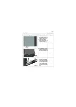
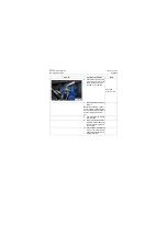
1. Loosen the plug at the top of
hydraulic oil tank breather
and press the bleed screw in
it to bleed the air;
Figures
Operation instruction
Tools
P18H00117
P18H00121
Summary of Contents for CLG835H
Page 2: ......
Page 4: ...Contents January 24 2017 CLG835H...
Page 6: ...1 2 General Information January 24 2017 CLG835H...
Page 38: ...1 34 Machine Inspection Table January 24 2017 CLG835H...
Page 156: ...3 2 Power Train System January 24 2017 CLG835H...
Page 214: ...3 2 Power Train System January 24 2017 CLG835H...
Page 272: ...3 60 Testing and adjustment January 24 2017 Power Train Test CLG835H...
Page 276: ...4 4 Hydraulic System January 24 2017 CLG835H...
Page 552: ...6 2 Driver s Cab System January 24 2017 CLG835H...
Page 608: ...7 2 Structure January 24 2017 CLG835H...
Page 662: ...8 4 Electrical System January 24 2017 CLG835H...
Page 677: ...8 19 January 24 2017 Structure Function Principle CLG835H Power System P18E00014...

