4-113
January 24, 2017
Removal and Installation
CLG835H
Work hydraulic system
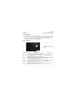
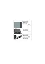
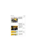
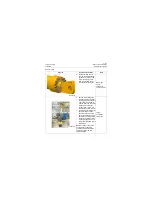
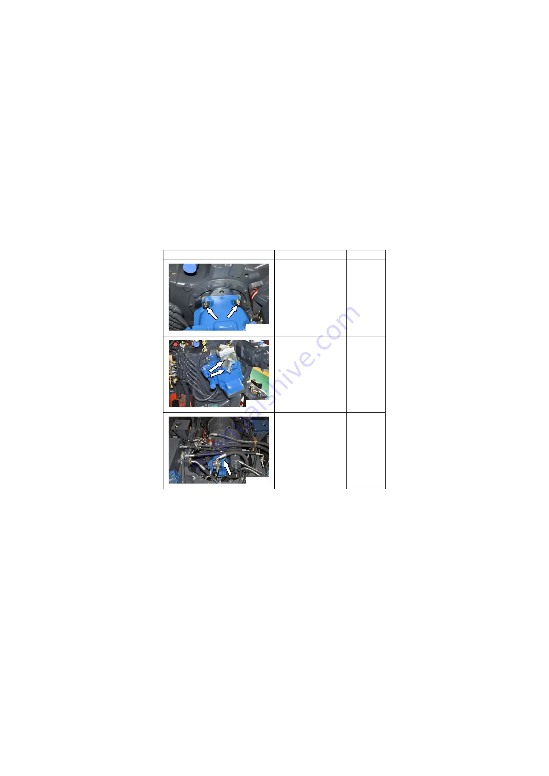
3. When the spline shaft is
coupled with gearbox, install
the nut to the stud bolt and
tighten it with torque
160±20Nm\ 118±14.8lbf·ft
Open-end
wrench: 21mm;
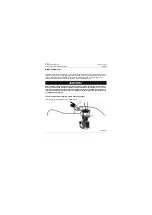
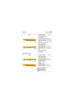
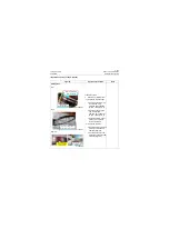
4. Install the plate, check valve
to the plunger pump opening
with the tightening torque of
flange mounting bolt
145±15Nm\ 107±11.1lbf·ft
Open-end
wrench: 21mm;
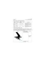
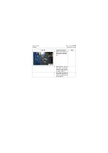
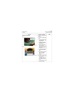
5. Connect the return oil hose
of the plunger pump housing
with the tightening torque of
hose joint 89
±
4Nm\ 65.6
±
3.0lbf·ft
Open-end
wrench: 32mm;
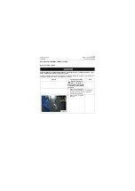
Figures
Operation instruction
Tools
P18H00133
P18H00134
P18H00135
Summary of Contents for CLG835H
Page 2: ......
Page 4: ...Contents January 24 2017 CLG835H...
Page 6: ...1 2 General Information January 24 2017 CLG835H...
Page 38: ...1 34 Machine Inspection Table January 24 2017 CLG835H...
Page 156: ...3 2 Power Train System January 24 2017 CLG835H...
Page 214: ...3 2 Power Train System January 24 2017 CLG835H...
Page 272: ...3 60 Testing and adjustment January 24 2017 Power Train Test CLG835H...
Page 276: ...4 4 Hydraulic System January 24 2017 CLG835H...
Page 552: ...6 2 Driver s Cab System January 24 2017 CLG835H...
Page 608: ...7 2 Structure January 24 2017 CLG835H...
Page 662: ...8 4 Electrical System January 24 2017 CLG835H...
Page 677: ...8 19 January 24 2017 Structure Function Principle CLG835H Power System P18E00014...


