


4-118
Removal and Installation
January 24, 2017
Work hydraulic system
CLG835H
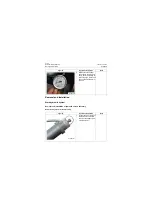
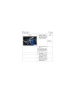
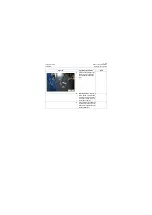
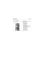
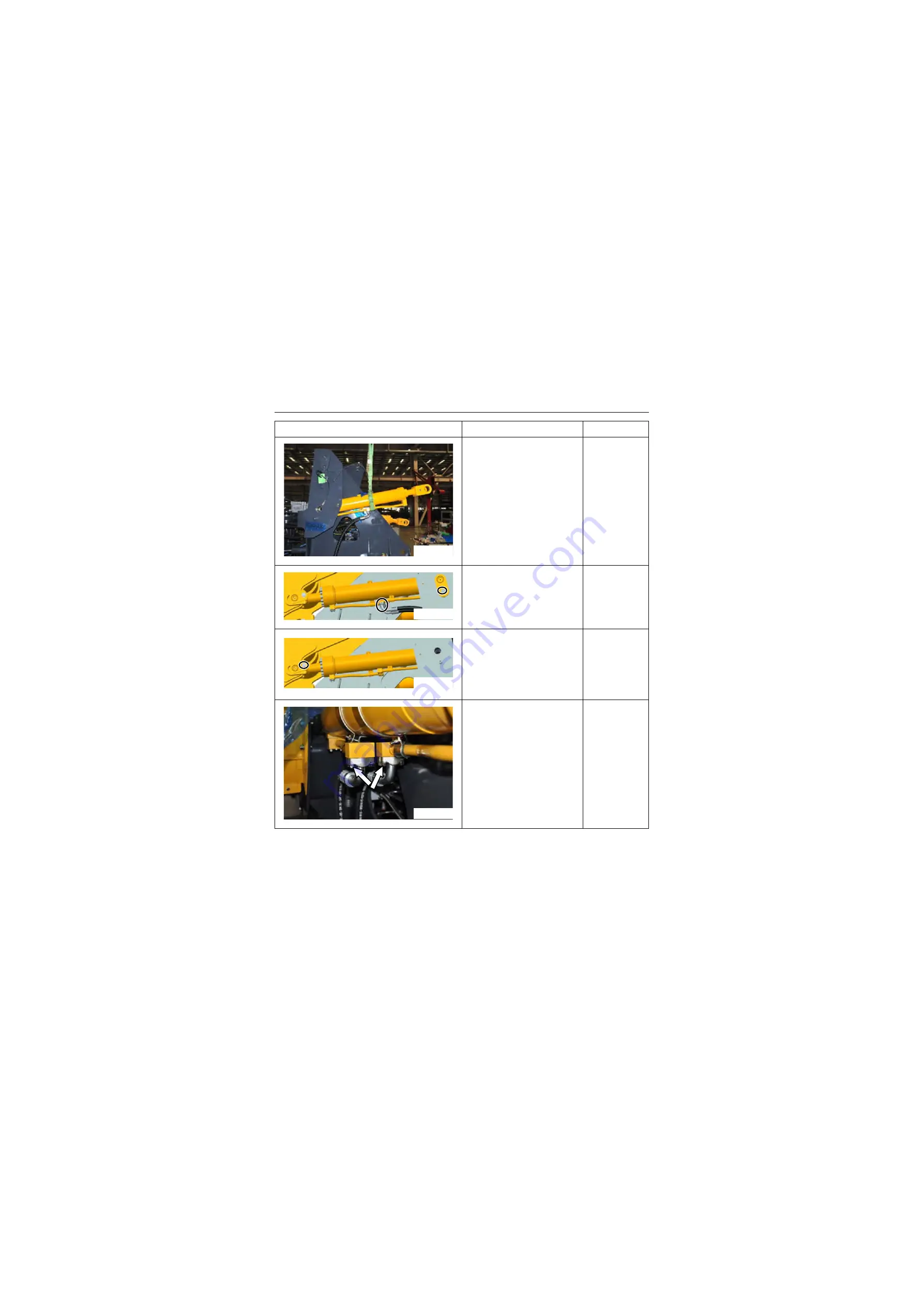
3. Lift and place the cylinder to
the proper position with
proper sling
4. Install rear pin shaft of boom
cylinder, and tighten mount-
ing bolt of pin shaft to
90±12Nm\ 66.4±8.9lbf·ft.
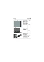
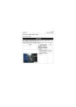
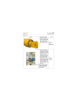
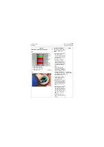
5. Align the pin hole of boom
cylinder piston rod connect-
ing fork with that of boom,
and then insert the pin shaft
into the pin hole, tighten
mounting bolt of pin shaft to
310±45Nm\ 228.6±33.2lbf·ft.
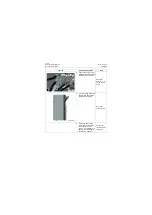
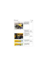
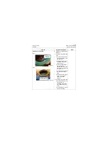
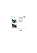
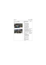
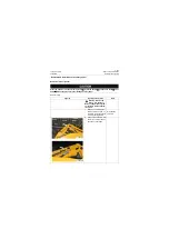
6. Connect the big and small
cavity hoses of boom cylin-
der, tighten the plate bolt to
72±6Nm\ 53.1±4.4lbf·ft.
Figures
Operation instruction
Tools
P18H00146
P18H00147
P18H00148
P18H00149
Summary of Contents for CLG835H
Page 2: ......
Page 4: ...Contents January 24 2017 CLG835H...
Page 6: ...1 2 General Information January 24 2017 CLG835H...
Page 38: ...1 34 Machine Inspection Table January 24 2017 CLG835H...
Page 156: ...3 2 Power Train System January 24 2017 CLG835H...
Page 214: ...3 2 Power Train System January 24 2017 CLG835H...
Page 272: ...3 60 Testing and adjustment January 24 2017 Power Train Test CLG835H...
Page 276: ...4 4 Hydraulic System January 24 2017 CLG835H...
Page 552: ...6 2 Driver s Cab System January 24 2017 CLG835H...
Page 608: ...7 2 Structure January 24 2017 CLG835H...
Page 662: ...8 4 Electrical System January 24 2017 CLG835H...
Page 677: ...8 19 January 24 2017 Structure Function Principle CLG835H Power System P18E00014...


