4-125
January 24, 2017
Removal and Installation
CLG835H
Work hydraulic system
Cylinder head assembly
Fig. I
Fig 2
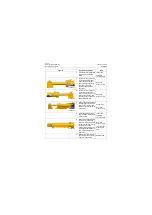
2. Inspection of cylinder head
assembly:
1) Inspection of cylinder head
seal:
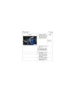
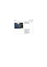
a. Check whether the dust
cover is scratched, worn
and damaged.
b. Check whether Y-seal is
scratched, worn, dam-
aged and burnt.
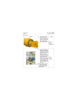
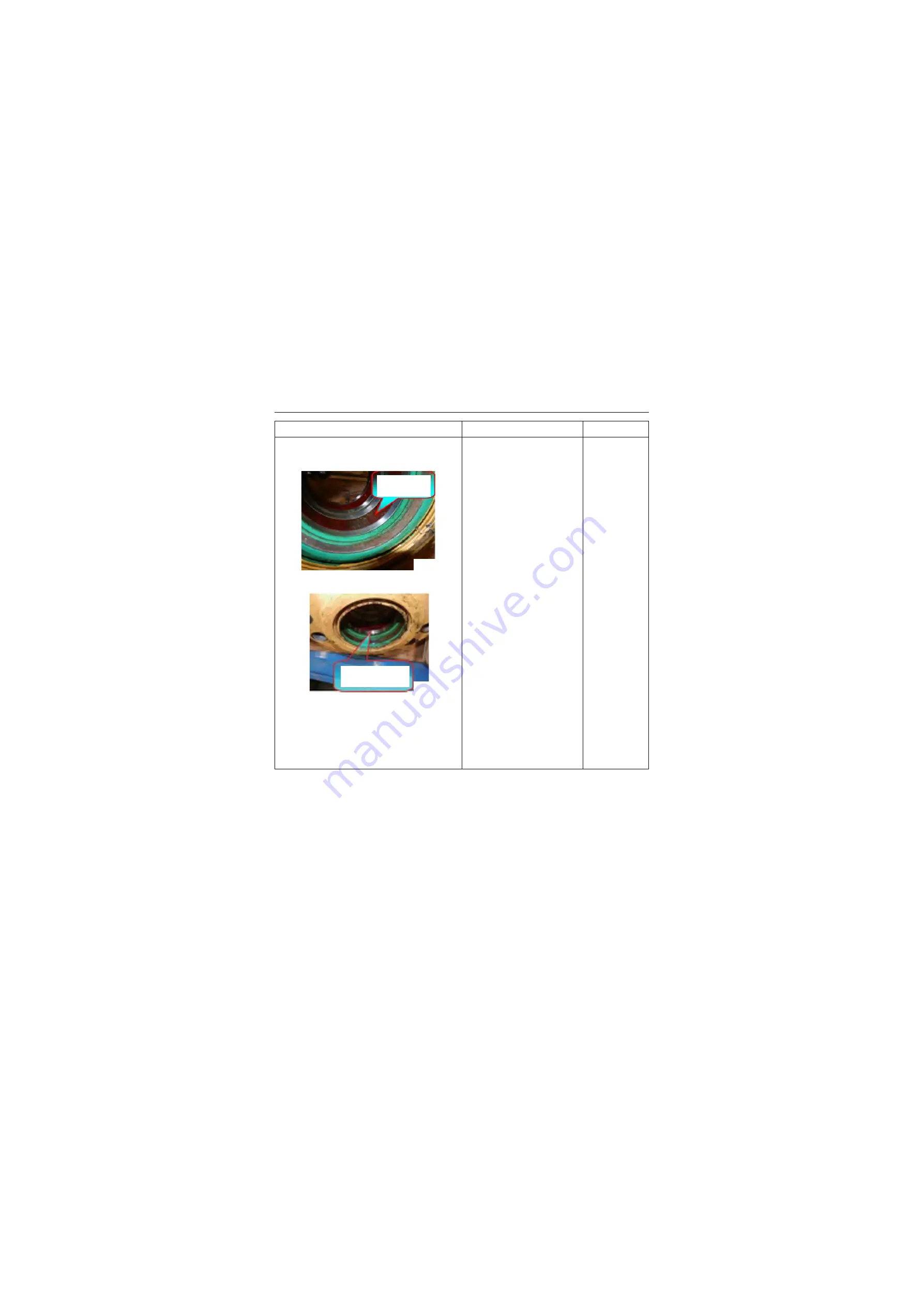
c. Check whether support
ring is scratched,
strained, worn, burnt and
attached with foreign mat-
ter. (Figure 1)
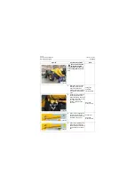
d. Check whether the buffer
ring is worn and dam-
aged.
e. Check whether O-ring at
static seal of cylinder
head is worn and
trimmed.
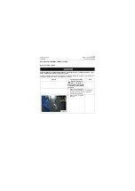
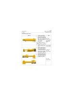
6) Inspection of cylinder head:
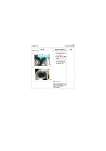
a. Check whether the cylin-
der head bore is
scratched, strained and
eccentrically worn (Fig-
ure 2).
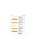
b. Check each part of cylin-
der head for crack.
Figures
Operation instruction
Tools
P18H00161
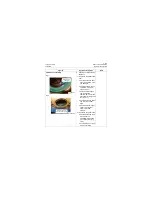
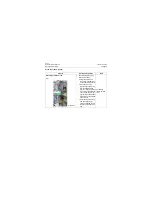
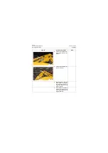
Support ring
has paint
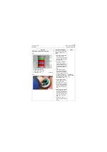
P18H00162
Cylinder head inner
hole has leaning wear
Summary of Contents for CLG835H
Page 2: ......
Page 4: ...Contents January 24 2017 CLG835H...
Page 6: ...1 2 General Information January 24 2017 CLG835H...
Page 38: ...1 34 Machine Inspection Table January 24 2017 CLG835H...
Page 156: ...3 2 Power Train System January 24 2017 CLG835H...
Page 214: ...3 2 Power Train System January 24 2017 CLG835H...
Page 272: ...3 60 Testing and adjustment January 24 2017 Power Train Test CLG835H...
Page 276: ...4 4 Hydraulic System January 24 2017 CLG835H...
Page 552: ...6 2 Driver s Cab System January 24 2017 CLG835H...
Page 608: ...7 2 Structure January 24 2017 CLG835H...
Page 662: ...8 4 Electrical System January 24 2017 CLG835H...
Page 677: ...8 19 January 24 2017 Structure Function Principle CLG835H Power System P18E00014...


