4-131
January 24, 2017
Removal and Installation
CLG835H
Work hydraulic system
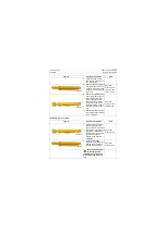
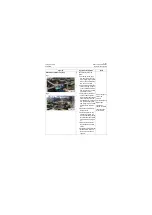
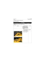
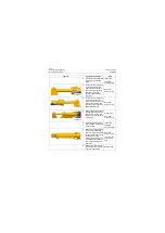
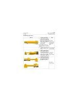
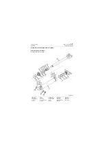
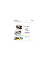
Assembly of piston rod group
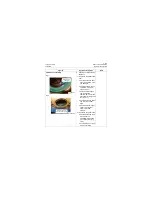
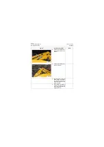
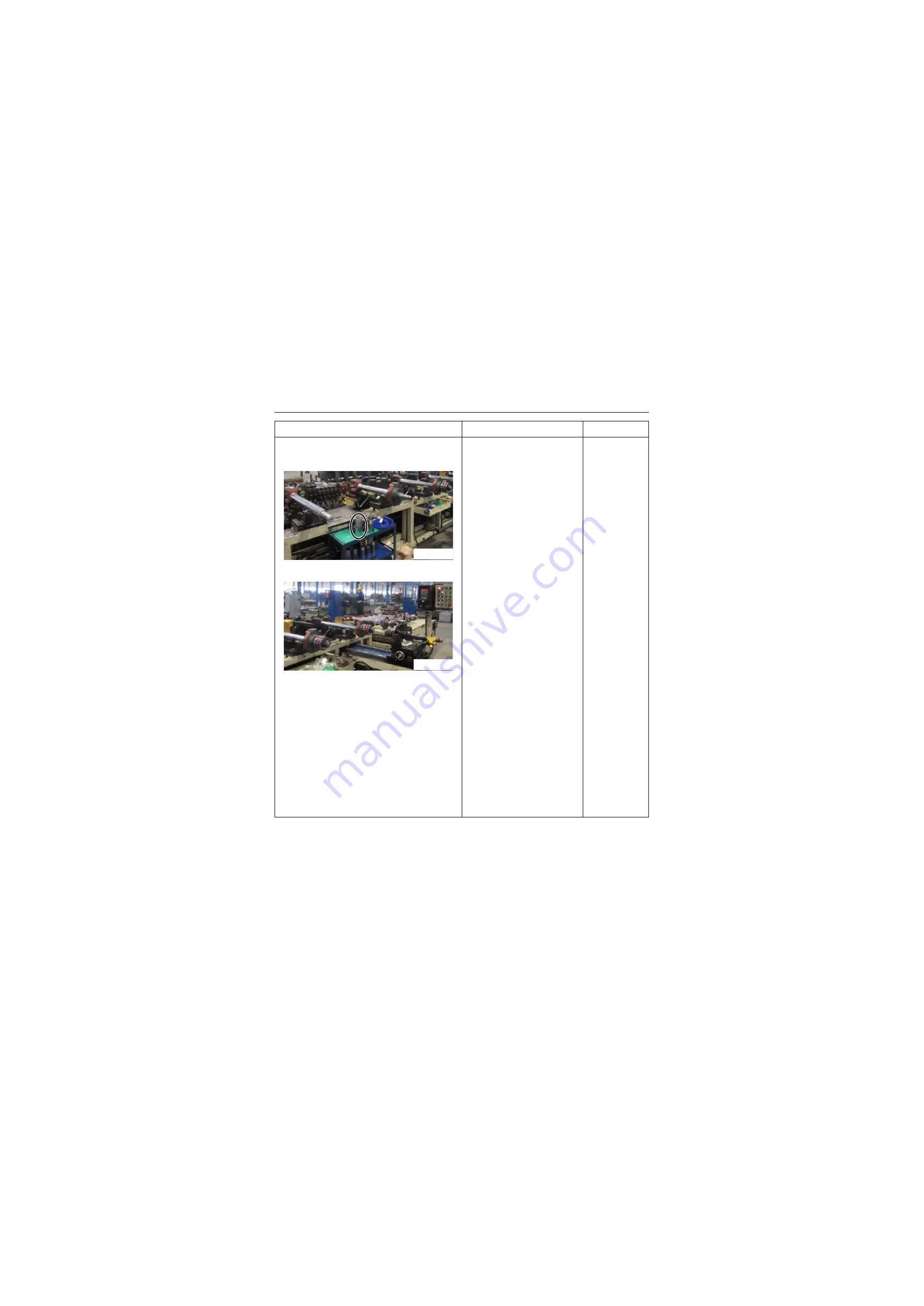
Fig. I
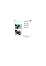
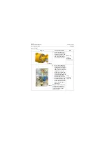
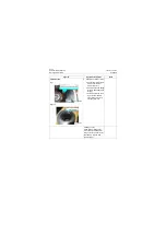
Fig 2
3. Assembly of piston rod
group:
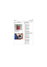
a. Fix the lug (boom cylin-
der: dual-lug, bucket cyl-
inder: single lug) of piston
rod on the special tooling
to make it not rotate.
b. Put the thread protective
sleeve (red ring in figure
1) on the thread at small
end of piston rod to avoid
scratching the seal.
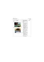
c. Apply clean hydraulic oil
on the surface of piston
rod and push the cylinder
head (dust ring side fac-
ing towards the rod head)
into the rod body (green
ring in figure 1) along with
axial direction of piston
rod.
d. Remove the thread pro-
tective sleeve.
e. Install the piston to the
small end of piston rod
with the tightening tooling
for piston and then tighten
it with blower gun (figure
2).
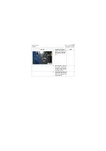
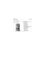
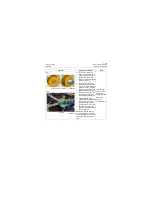
f. Install the steel ball into
the threaded hole of the
piston.
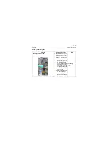
g. Screw the setscrew to the
threaded hole of the pis-
ton with inner hexagon
spanner.
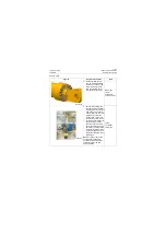
Fixing tooling for
piston rod
Thread
protective sleeve
Blower gun
Tightening
tooling for piston
Inner hexagon
wrench: 4mm
Figures
Operation instruction
Tools
P18H00172
P18H00173
Summary of Contents for CLG835H
Page 2: ......
Page 4: ...Contents January 24 2017 CLG835H...
Page 6: ...1 2 General Information January 24 2017 CLG835H...
Page 38: ...1 34 Machine Inspection Table January 24 2017 CLG835H...
Page 156: ...3 2 Power Train System January 24 2017 CLG835H...
Page 214: ...3 2 Power Train System January 24 2017 CLG835H...
Page 272: ...3 60 Testing and adjustment January 24 2017 Power Train Test CLG835H...
Page 276: ...4 4 Hydraulic System January 24 2017 CLG835H...
Page 552: ...6 2 Driver s Cab System January 24 2017 CLG835H...
Page 608: ...7 2 Structure January 24 2017 CLG835H...
Page 662: ...8 4 Electrical System January 24 2017 CLG835H...
Page 677: ...8 19 January 24 2017 Structure Function Principle CLG835H Power System P18E00014...

