


4-152
Removal and Installation
January 24, 2017
Work hydraulic system
CLG835H
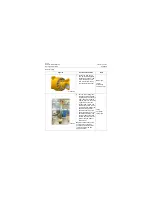
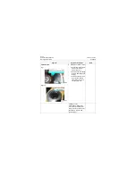
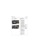
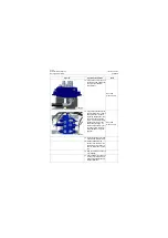
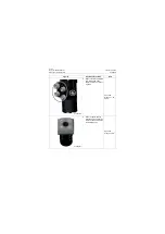
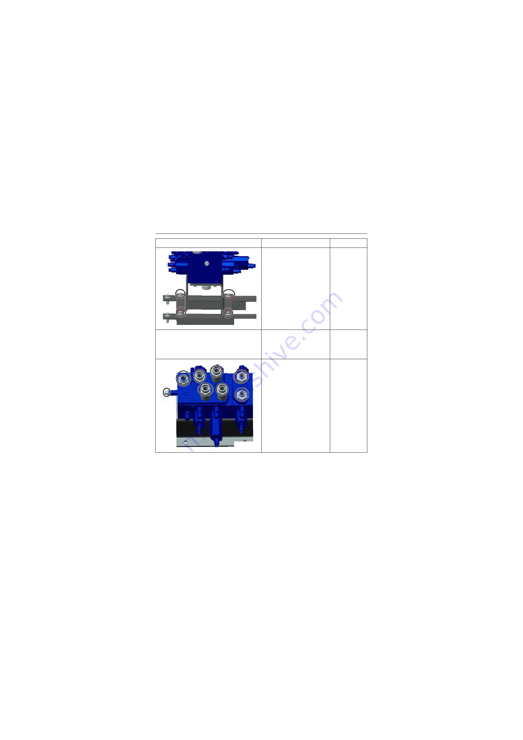
7. Unscrew the 4 fastening
bolts, nuts from control valve
and place it together with the
bolts, nuts.
Open-end
wrench:
15mm.
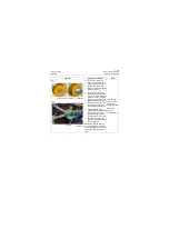
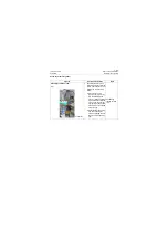
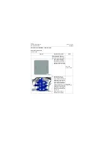
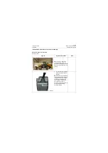
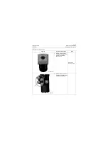
8. Lift the control valve slowly
and levelly and move out
from the access port of the
control valve of the front
frame slowly;
Lifting rope,
crane
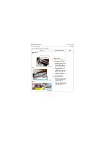
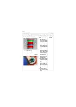
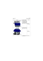
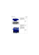
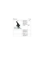
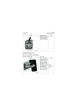
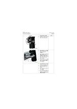
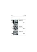
9. Place the control valve on
the ground; remove the tran-
sition joint, mounting plate
installed on the valve body
and mask oil ports of control
valve.
Open-end
wrench: 13, 19,
41mm
Figures
Operation instruction
Tools
P18H00215
P18H00216
Summary of Contents for CLG835H
Page 2: ......
Page 4: ...Contents January 24 2017 CLG835H...
Page 6: ...1 2 General Information January 24 2017 CLG835H...
Page 38: ...1 34 Machine Inspection Table January 24 2017 CLG835H...
Page 156: ...3 2 Power Train System January 24 2017 CLG835H...
Page 214: ...3 2 Power Train System January 24 2017 CLG835H...
Page 272: ...3 60 Testing and adjustment January 24 2017 Power Train Test CLG835H...
Page 276: ...4 4 Hydraulic System January 24 2017 CLG835H...
Page 552: ...6 2 Driver s Cab System January 24 2017 CLG835H...
Page 608: ...7 2 Structure January 24 2017 CLG835H...
Page 662: ...8 4 Electrical System January 24 2017 CLG835H...
Page 677: ...8 19 January 24 2017 Structure Function Principle CLG835H Power System P18E00014...


