4-155
January 24, 2017
Removal and Installation
CLG835H
Work hydraulic system
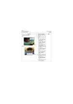
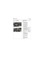
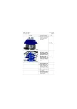
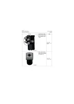
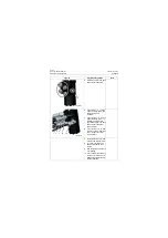
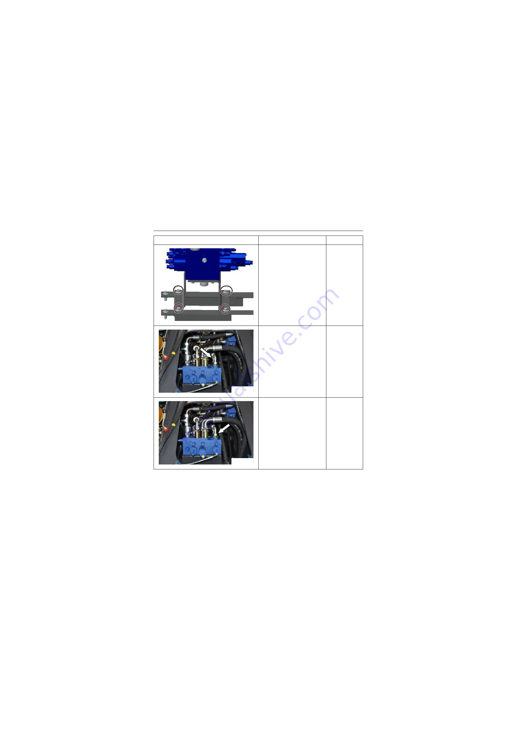
3. Install the control valve fas-
tening bolts and nuts with
the torque of 90±10Nm\
66.4±7.4lbf·ft
Open-end
wrench: 15mm
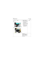
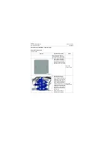
4. Connect the multi-functional
small cavity hose, tighten
the hose joint to 89
±
4Nm\
65.6
±
3.0lbf·ft
Open-end
wrench: 32mm;
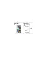
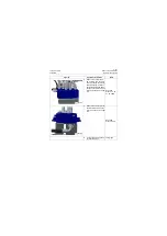
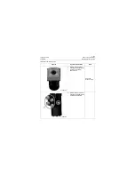
5. Connect the multi-functional
big cavity hose, tighten the
hose joint to 89
±
4Nm\ 65.6
±
3.0lbf·ft
Open-end
wrench: 32mm;
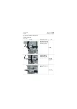
Figures
Operation instruction
Tools
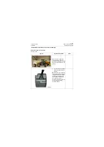
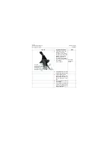
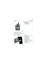
P18H00220
P18H00221
P18H00222
Summary of Contents for CLG835H
Page 2: ......
Page 4: ...Contents January 24 2017 CLG835H...
Page 6: ...1 2 General Information January 24 2017 CLG835H...
Page 38: ...1 34 Machine Inspection Table January 24 2017 CLG835H...
Page 156: ...3 2 Power Train System January 24 2017 CLG835H...
Page 214: ...3 2 Power Train System January 24 2017 CLG835H...
Page 272: ...3 60 Testing and adjustment January 24 2017 Power Train Test CLG835H...
Page 276: ...4 4 Hydraulic System January 24 2017 CLG835H...
Page 552: ...6 2 Driver s Cab System January 24 2017 CLG835H...
Page 608: ...7 2 Structure January 24 2017 CLG835H...
Page 662: ...8 4 Electrical System January 24 2017 CLG835H...
Page 677: ...8 19 January 24 2017 Structure Function Principle CLG835H Power System P18E00014...


