4-158
Removal and Installation
January 24, 2017
Work hydraulic system
CLG835H
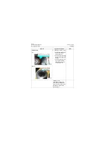
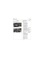
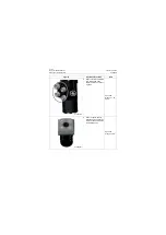
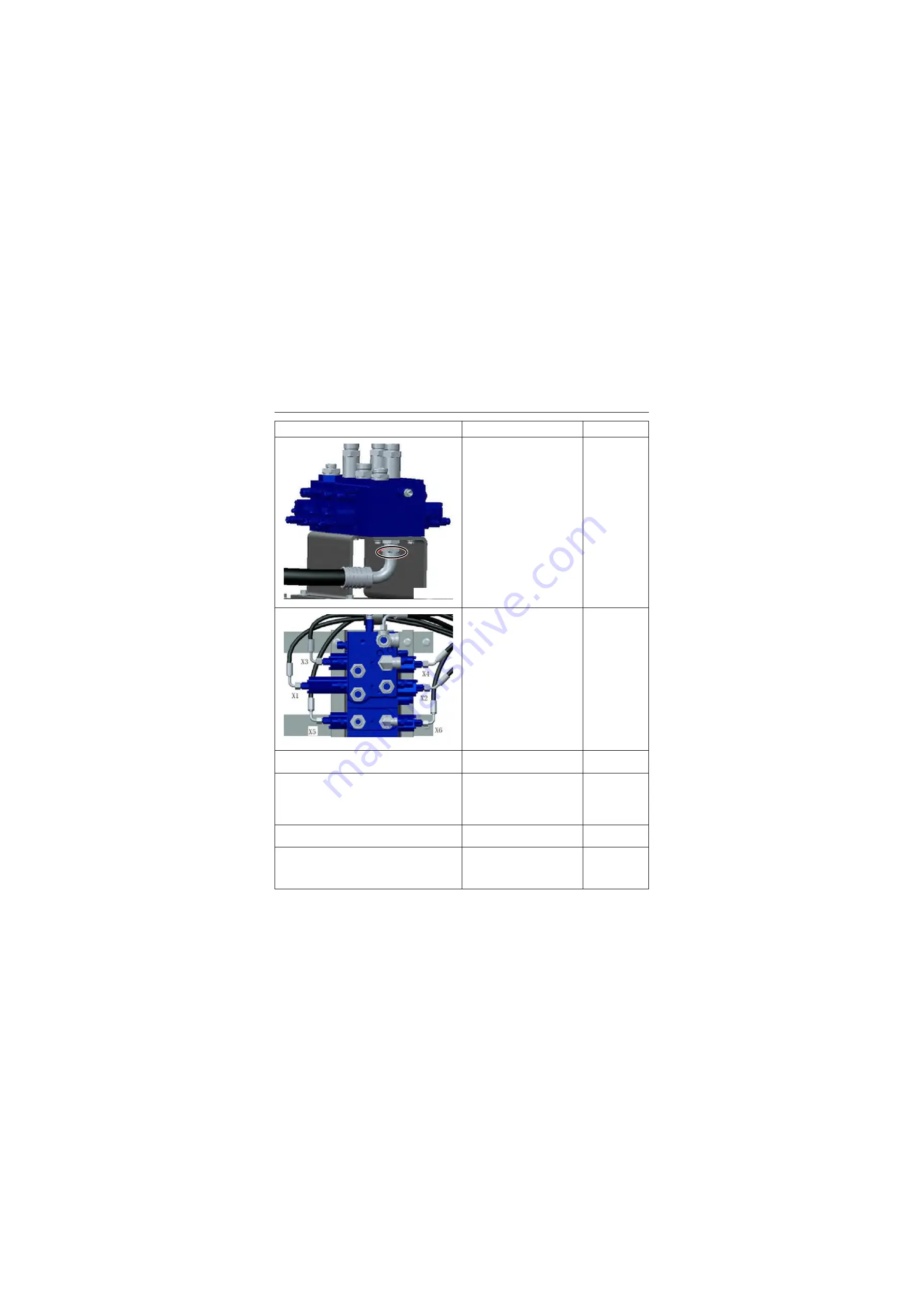
12. Connect the oil inlet hose of
the control valve, tighten the
hose joint to 179±8Nm\
132±5.9lbf·ft
Open-end
wrench: 44mm
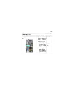
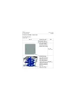
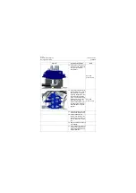
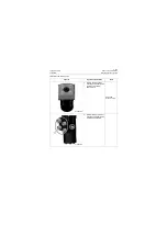
13. Connect the pilot hose to the
control valve by the symbols
during removal: "X1-boom
big cavity linkage pilot", "X2-
boom small cavity linkage
pilot", "X3-bucket big cavity
linkage pilot", "X4-bucket
small cavity linkage pilot" ,
"X5-multi-functional big cav-
ity linkage pilot", "X6-multi-
functional small cavity link-
age pilot".
Open-end
wrench: 19mm
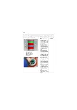
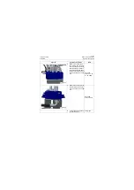
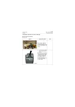
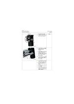
14. Fill the hydraulic oil, start the
machine and idle it for 5min
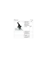
15. Tilt back and dump the
bucket, raise and lower the
boom slowly for at least 10
times to bleed the air in the
line.
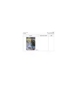
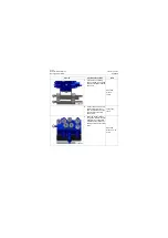
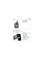
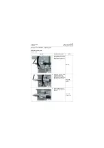
16. Stop the machine and check
it for leakage.
17. Check whether the hydraulic
oil level is normal, and if not,
please fill the hydraulic oil to
the specified level
Figures
Operation instruction
Tools
P18H00229
P18H00230
Summary of Contents for CLG835H
Page 2: ......
Page 4: ...Contents January 24 2017 CLG835H...
Page 6: ...1 2 General Information January 24 2017 CLG835H...
Page 38: ...1 34 Machine Inspection Table January 24 2017 CLG835H...
Page 156: ...3 2 Power Train System January 24 2017 CLG835H...
Page 214: ...3 2 Power Train System January 24 2017 CLG835H...
Page 272: ...3 60 Testing and adjustment January 24 2017 Power Train Test CLG835H...
Page 276: ...4 4 Hydraulic System January 24 2017 CLG835H...
Page 552: ...6 2 Driver s Cab System January 24 2017 CLG835H...
Page 608: ...7 2 Structure January 24 2017 CLG835H...
Page 662: ...8 4 Electrical System January 24 2017 CLG835H...
Page 677: ...8 19 January 24 2017 Structure Function Principle CLG835H Power System P18E00014...

